
Gear manufacturing
How are gears manufactured?
In the changing gear manufacturing landscape, choosing the most efficient and accurate machining method and gear tooling is essential. Component and production processes and batch size determine the choice of tool and gear manufacturing method.
Gear machining is performed during the soft stage process, where the challenge is often to acquire close dimensional tolerances. Careful preparation for the hardening stage gives a relatively straight-forward hard part turning operation, followed by hard machining of the gears. In hard part turning, predictable machining and good surface finishing is essential. All this should be combined with cost-effectiveness.
The gear machining process is going to change substantially due to e-mobility, new transmission design and the need to be both flexible and productive at the same time. Focus will move away from the common conventional gear machine tools and instead, multitask machining of gear/spline components will become the norm. Power skiving will be in focus since it will replace shaping, broaching and spline rolling, along with hobbing to some extent.Gear quality
Gears are normally classified according to a standard specifying tolerance requirements for the gear wheel after the machining operation. The most common standard for cylindrical gear classification is DIN 3962, where different gear parameters are measured and classified on a 1–12 scale. Other customer-specific standards are also common but they all have more or less the same evaluation parameters as the DIN 3962 standard.
Gear quality class is generally determined by component requirements and depends on of the gear wheel application area.
Other demands for good gear quality are:
- High-quality tools
- Clean contact surfaces
- Minimum run-out both on tool and workpiece
- Stable clamping
- Accurate and stable machine
How to apply gear manufacturing
The gear tool profile typically needs to be tailored to the specific gear wheel. This means that size and shape of a tooth gap must be completely matched by the tool.
Important considerations when ordering a gear milling tool:
- Module size
- Pressure angle
- Gear tooth profile (protuberance, tip relief or tip chamfer)
- Addendum modification factor
- Tip- and root diameter
- Helix angle
- Gear quality requirements
- Possible tool diameter range (min-max)
- Coupling type and size
A complete gear wheel drawing is preferable and gives all the necessary information.
Gear manufacturing methods
These new cutting technologies are about to transform the gear manufacturing business. How manufacturers respond to this technology shift will shape the future competitive landscape.
- InvoMilling™
- Power skiving
- Disc cutting for small and mid volume sizes
- Gear hobbing
InvoMilling™
What is InvoMilling™ ?
Machining gears normally requires dedicated tools for the specific gear profile. InvoMilling™ is a process for machining external gears, splines and straight bevel gears and allows for in-house gear milling in standard machines. By changing the CNC program instead of changing the tool, one tool set can be used for many gear profiles. Complete components can be machined in one set-up using multi-task machines or a five-axis machining centre, thus InvoMilling™ can reduce lead times and shorten total manufacturing time significantly.InvoMilling™ advantages
- Flexibility – same tools for many gear profiles
- Gear machining in multi-task machines and five-axis machining centres
- Complete components in one machine and one set-up
- More environmentally-friendly - runs dry, does not use cutting oil
When to use the InvoMilling™ process
- For machining external gears and splines, double helical gears, herringbone gears and straight bevel gears
- When gear components for need to be produced without the need for dedicated tools or machines
- When short lead times are crucial
- Can use with or without flank corrections
- Module range: 0.8‒100
- For roughing to finishing
- For small to medium batch production
How to apply InvoMilling™
Watch the film and see how to generate a finished CNC program with the InvoMilling™ CAD/CAM software in three easy steps:
- Define your gear geometry by importing the gear data from your component drawing.
- Choose your machining strategy, add roughing and finishing operations and select tools to be used from the tool library.
- Simulate the machining process to verify tool paths before automatically generating a CNC program for your machine.
Power skiving
What it is power skiving?
Power skiving is a continuous cutting process that is multiple times faster than shaping and more flexible than broaching. Even though power skiving as a concept has been around for over a century, it is not until recently that the development has taken a new turn. As a result of the rapid progress of more robust and rigid machines and synchronized spindles, a wider use of power skiving is now quickly becoming a reality.
Power skiving can be applied to both internal and external gears and splines, but is especially productive when it comes to internal machining. The method works particularly well in mass production, where short lead times are decisive. For small to medium batch production, the flexible InvoMilling™ technology is recommended.Power skiving advantages
- One set-up machining, which shortens production time, improves quality and reduces handling and logistics costs
- Capable of machine close to shoulders, allowing greater freedom in component design
- Environmental and operator friendly
- Runs very efficiently in dry conditions
- Significantly reduced total production time in comparison to processes with broaching, shaping and hobbing
- Manageable and predictable component machining
- Component quality achieved is on par with or better than what is attainable with comparable gear milling solutions
- Can be applied in dedicated machines, multi-task machines and machining centres
When to use the power skiving process
- Internal and external gears and splines
- Cylindrical spur and helical gears
- Roughing to finishing
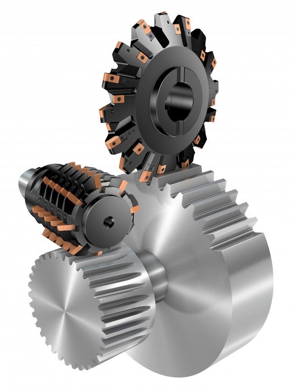
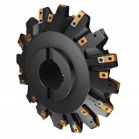
Disc cutting
What is disc cutting?
Disc cutting is a process where one tooth gap at a time is cut. Disc cutting methods are easily applied in machining centres, multi-task machines and turning centres, making it possible to machine complete components in one set-up. Splines typically made in hobbing machines or sub-contracted out can instead be machined in-house with existing machines when using disc cutting technology. Thus, disc cutting does not require a large initial investment.Disc cutting advantages
- Spline milling in machining centres, multi-task machines and turning centres
- Low investment costs
- Machine splines in existing machines instead of investing in a hobbing machine
- Less time and cost spent on logistics
- No need to move components between machines or workshops
- No need to re-sharpen and re-coat high speed steel (HSS) tools
- High cutting speeds
- Capable of cutting difficult materials
- Dry machining reduces lead times and coolant costs, while contributing to a more eco- and worker-friendly environment
- Cost-efficient solution for small to medium batch sizes
When to use the disc cutting process
- External splines
- Roughing to finishing
- All machine types
- Dry machining
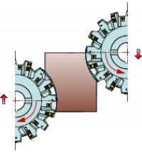
Down milling
Up milling
Gear hobbing
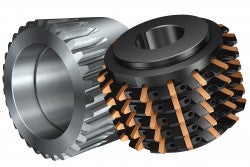
What is gear hobbing?
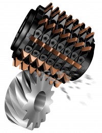
Hobbing is a gear manufacturing process in which gear teeth are generated through a series of cuts with a helical cutting tool. The hob and gear blank are rotated continuously until all teeth are cut. Hobbing is only possible for external gears.Gear hobbing advantages
- Reduced total cost per gear wheel compared to HSS tools
- High cutting speeds
- Longer tool life, reduced downtime
- Easy and repeatable tool indexing and handling
- No additional regrinding or recoating costs
When to use the gear hobbing process
- Roughing, semi-finishing, finishing
- Gear profiles according to DIN 3972-2
- Module range: 3–10
- Hobbing machines, multi-task machines, 5-axis machines
How to apply gear hobbing
- All teeth cut different chips. Tool life is limited by the heaviest cuts and thickest chips. In order to evaluate chip thickness, calculate the maximum chip thickness hex to determine axial feed rate. Max hex is calculated according to Hoffmeister’s equation
- Recommended max hex = 0.18–0.22 mm (0.007–0.009 inch)
- Use hob shifting if possible in order to improve tool life
- Dry milling is to prefer with carbide tools and will give a better tool life compared to wet milling
- If possible, use down milling for better tool life
Steam turbine shaft
Turbine shafts are mainly machined through turning and groove-cutting operations... keyboard_arrow_right
Success stories
Component: Main gear Workpiece material: Low-alloy steel 16MnCr5, CMC 02.1/02.2... keyboard_arrow_right
InvoMilling™
ไฮไลต InvoMilling™ is a process for machining external gears, splines and straight... keyboard_arrow_right
Turbine blade
Blade machining moves to a new level Competitive manufacturing blades for steam... keyboard_arrow_right
