Milling troubleshooting tips about vibration issues, chip jamming, re-cutting of chips, un-satisfactory surface finish, burr formation, machine power and tool wear are presented in the following table.
Cause
Solution
Vibration
Weak fixture
Assess the direction of the cutting forces and provide adequate support or improve the fixture
Reduce the cutting forces by decreasing the cutting depth, ap
Select a coarse and differentially pitched cutter with a more positive cutting action
Select a geometry with a small corner radius and small parallel land
Select a fine-grain, uncoated insert, or a thinner coating
Avoid machining where the workpiece has poor support against the cutting forces
Axially weak workpiece
Consider a square shoulder cutter (90-degree entering angle) with positive geometry
Select an insert with L-geometry
Decrease axial cutting force – lower depth of cut, smaller corner radius and parallel land
Select a coarse-pitch cutter with differential pitch
Check tool wear
Check tool holder run-out
Improve clamping of tool
Too long tool overhang
Minimize overhang
Use coarse-pitch cutters with differential pitch
Balance radial and axial cutting forces – 45 degree entering angle, large corner radius or round insert cutter
Increase feed per tooth
Use a light-cutting insert geometry
Reduce axial depth of cut, af
Use up milling in finishing
Use oversized cutters and Coromant Capto® coupling adaptors
For solid carbide end mills and exchangeable-head mills, try a tool with fewer teeth and/or a higher helix angle
Milling square shoulder with weak spindle
Select smallest possible cutter diameter
Select a positive and light-cutting cutter and insert
Try up milling
Check spindle deflection to see if acceptable for machine
Irregular table feed
Try up milling
Tighten machine feed mechanism: adjust the feed screw on CNC machine
Adjust the locking screw or replace the ball screw on conventional machines
Cutting data
Reduce cutting speed, vc
Increase feed, fz
Change cutting depth, ap
Bad stability
Reduce overhang
Improve stability
Vibration in corners
Program large corner radii with reduced feed rate
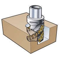
Chip jamming Common obstacle when full slotting – especially in long-chipping materials
Insert corner damage
Edge chipping and breakage
Re-cutting of chips
Improve chip evacuation by using rich and well directed cutting fluid or compressed air
Reduce feed, fz
Split deep cuts into several passes
Try up milling in deep slotting
Use coarse pitch cutters
Use solid carbide end mills or exchangeable-head mills with two or maximum three cutting edges and/or a higher helix angle
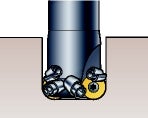
Re-cutting of chips Appears in full slotting and pocketing – especially in titanium. Also common when milling deep cavities and pockets on vertical machines.
Cutting edge fractures
Harmful for tool life and security
Chip jamming
Evacuate chips effectively by compressed air or copious cutting fluid flow – preferably internal coolant
Change cutter position and tool path strategy
Reduce feed, fz
Split deep cuts into several passes
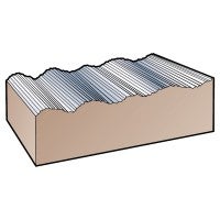
Unsatisfactory surface finish
Excessive feed per revolution
Set cutter axially or classify inserts. Check height with indicator
Check spindle run-out and cutter mounting surfaces
Decrease feed per rev to max. 70% of the width of the parallel land
Use wiper inserts if possible (for finishing operations)
To achieve optimized cutting data, best possible component quality and tool life, always remember to check the insert/cutting edge after machining. Use this list of causes and solutions to different forms of insert wear as a reference for successful milling.
Cause
Solution
Flank wear Rapid wear causing poor surface finish or out of tolerance.
Cutting speed too high
Insufficient wear resistance
Feed, fz, too low
Reduce cutting speed, vc
Select a more wear-resistant grade
Increase feed, fz
Flank wear Excessive wear causing short tool life.
Vibration
Re-cutting of chips
Burr formation on component
Poor surface finish
Heat generation
Excessive noise
Increase feed, fz
Use down milling
Evacuate chips effectively using compressed air
Check recommended cutting data
Flank wear Uneven wear causing corner damage.
Tool run-out
Vibration
Short tool life
Bad surface finish
High noise level
Radial forces too high
Reduce run-out below 0.02 mm (0.0008 inch)
Check chuck and collet
Minimize tool protrusion
Use fewer teeth in cut
Choose a larger tool diameter
For solid carbide end mills and exchangeable-head mills, select a higher helix geometry (gp ≥45°)
Split axial cutting depth, ap, into more than one pass
Reduce feed, fz
Reduce cutting speed, vc
HSM requires shallow passes
Improve clamping of tool and workpiece
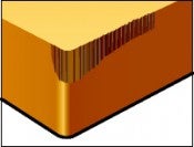
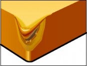
Crater wear Excessive wear causing a weakened edge. Cutting edge breakthrough on the trailing edge causes poor surface finish.
Diffusion wear due to cutting temperatures that are too high on the rake face
Select an Al203 coated grade
Select a positive insert geometry
Reduce the speed to obtain a lower temperature, and then reduce the feed
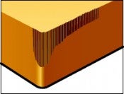
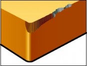
Plastic deformation Plastic deformation of edge, depression or flank impression, leading to poor chip control, poor surface finish and insert breakage.
Cutting temperature and pressure too high
Select a more wear resistant (harder) grade
Reduce cutting speed, vc
Reduce feed, fz
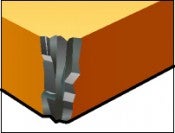
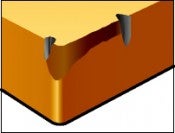
Chipping The part of the cutting edge not in cut is damaged by chip hammering. Both the top side and the support for the insert can be damaged, leading to poor surface texture and excessive flank wear.
The chips are deflected against the cutting edge
Select a tougher grade
Select an insert with a stronger cutting edge
Increase cutting speed, vc
Select a positive geometry
Reduce feed at the beginning of cut
Improve stability
Chipping Small cutting edge fractures (frittering) causing poor surface finish and excessive flank wear.
Grade too brittle
Insert geometry too weak
Built-up edge
Select a tougher grade
Select an insert with a stronger geometry
Increase cutting speed, vc, or select a positive geometry
Reduce feed at the beginning of cut
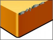
Notch wear Notch wear causing poor surface finish and risk of edge breakage.
Work hardening materials
Skin and scale
Reduce cutting speed, vc
Select a tougher grade
Use a stronger geometry
Use a cutting angle closer to 45 degrees
Use round inserts for best result
Use variable ap technique to prolong the wear
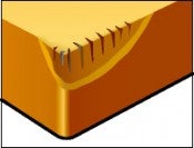
Thermal cracks Small cracks perpendicular to the cutting edge causing frittering and poor surface finish due to temperature variations.
Intermittent machining
Varying cutting fluid supply
Select a tougher grade with better resistance to thermal shocks
Cutting fluid should be applied copiously or not at all
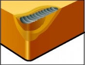
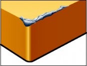
Built-up edge (BUE) Built-up edge causing poor surface finish and cutting edge frittering when the BUE is torn away.
Cutting zone temperature is too low
Very sticky material, such as low-carbon steel, stainless steels, and aluminium
Increase cutting speed, vc
Change to a more suitable insert geometry
Built-up edge (BUE) Workpiece material is welded to the cutting edge.