
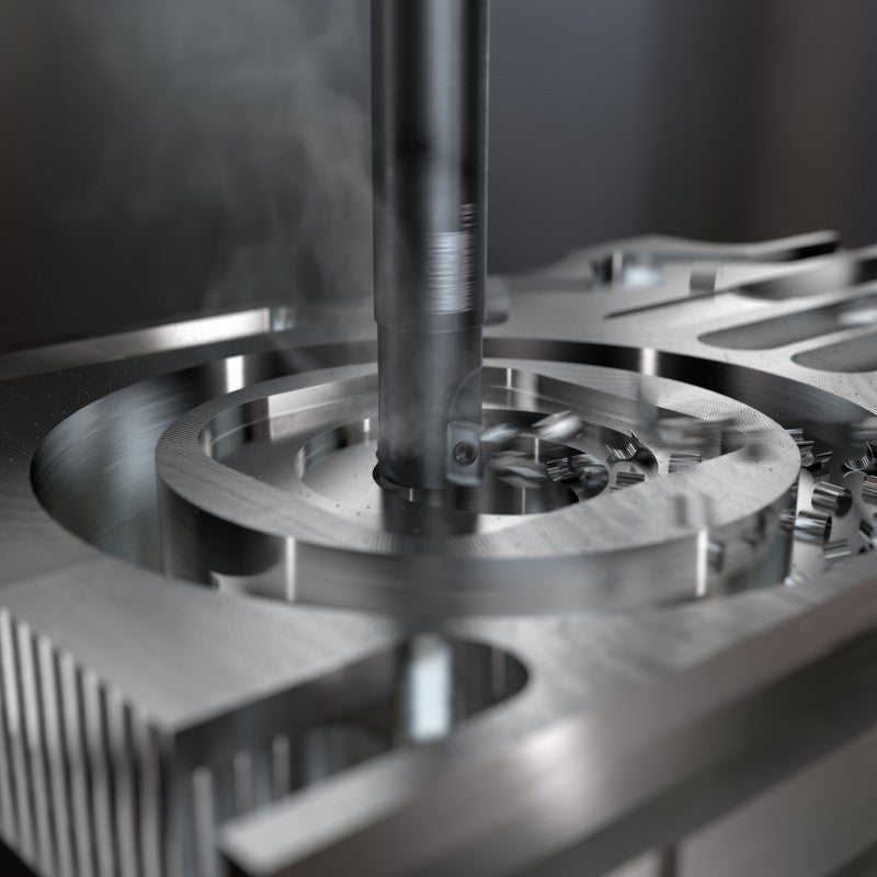
How to do milling in different materials
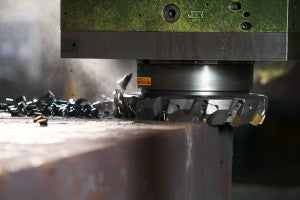
Milling steel
The machinability of steel differs depending on alloying elements, heat treatment and manufacturing process (forged, cast, etc.).
In soft, low carbon steels, built-up edge and burr formation on the workpiece are the main issues. In harder steels, the positioning of the cutter becomes more important to avoid edge chipping.
Recommendations
Always follow our recommendations when milling steel, such as positioning of the cutter to avoid a large chip thickness on exit, and to always consider to run dry without cutting fluid, especially in roughing operations.
Read more about steel materials
Milling stainless steel
Stainless steels can be categorized as ferritic/martensitic, austenitic and duplex (austenitic/ferritic), each with its own machining recommendations for milling.
Milling ferritic/martensitic stainless steel
Material Classification: P5.x
Ferritic stainless steel have a machinability that is comparable to low alloyed steel, and therefore, the recommendations for steel milling can be used.
Martensitic stainless steel has a higher work-hardening property and exerts very high cutting forces when entering the cut. Apply the correct tool path and roll-in method for best results and use higher cutting speed, vc, to overcome the work-hardening effect. Higher cutting speed an a tougher grade with reinforced cutting edge gives higher security.
Milling austenitic and duplex stainless steel
Material Classification: M1.x, M2.x and M3.x
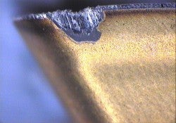
The dominant wear criteria when milling austenitic and duplex stainless steels are chipping on the edges due to thermal cracks, notch wear and built-up edge/smearing. On the component, burr formation and surface finish problems are the main issues.
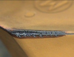
Thermal cracks
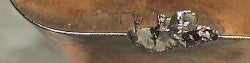
Edge chipping on the insert
Burr formation and bad surface finish
Recommendations in roughing
- Use high cutting speeds (vc = 150–250 m/min (492–820 ft/min)) to avoid built-up edge
- Run dry, without cutting fluid, to minimize problems with thermal cracks
Recommendations in finishing
- Cutting fluid, or preferably mist coolant/minimal lubrication, is sometimes necessary to improve the surface finish. There are less problems with thermal cracks when finishing because the heat generated in the cutting zone is lower
- With a cermet grade sufficient surface finish can be obtained without cutting fluid
- Feed, fz, that is too low can cause higher insert wear because the edge is cutting in the deformation hardened zone
Milling cast iron
There are five main types of cast iron:
- Grey Cast Iron (GCI)
- Nodular Cast Iron (NCI)
- Malleable Cast Iron (MCI)
- Compacted Graphite Iron (CGI)
- Austempered Ductile Iron (ADI)
Grey cast iron
Material Classification: K2.x
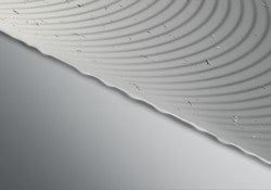
The dominant wear criteria when milling grey cast iron are abrasive flank wear and thermal cracks. On the component, frittering at the cutter exit side of the workpiece, and surface finish problems are the main issues.
Typical insert wear
Frittering on the component
Recommendations in roughing
- Preferably run dry, without cutting fluid, to minimize problems with thermal cracks. Use carbide inserts with thick coatings
- If workpiece frittering is a problem: Check flank wearLower the feed, fz, in order to reduce chip thicknessUse a more positive geometryPreferable use 65/60/45 degree cutters
- If cutting fluid must be used to avoid dust, etc. choose the wet milling grades
- Coated carbide is always the first choice, but ceramics can also be used. Note that the cutting speed, vc, should be very high, 800–1000 m/min (2624–3281 ft/min). Burr formation on the workpiece limits the cutting speed. Do not use cutting fluid
Recommendations in finishing
- Use carbide inserts with thin coatings, or, alternately, an uncoated carbide
- CBN grades can be used for finishing at high speeds. Do not use cutting fluid
Nodular cast iron
Material Classification: K3.x
The machinability of ferritic and ferritic/perlitic nodular cast iron is very similar to that of low alloyed steel. Therefore, the milling recommendations provided for steel materials should be used regarding selection of tools, insert geometries and grades.
Perlitic nodular cast iron is more abrasive, therefore cast iron grades are recommended.
Use PVD coated grades and wet machining for best machining capabilities.
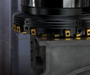
Compact graphite iron (CGI)
Material Classification: K4.x
Perlitic content less than 90%
This type of CGI, which often has a perlitic structure of around 80%, is the most common being milled. Typical components are engine blocks, cylinder heads and exhaust manifolds.
Cutter recommendations are the same as for grey cast iron; however, sharper, more positive insert geometries should be selected to minimize burr formation on the component.
Circular milling can be a very good alternative method to conventional cylinder boring in CGI.
Austempered ductile iron (ADI)
Material Classification: K5.x
Roughing is normally carried out in the non-hardened condition and can be compared with milling of a high alloyed steel.
The finishing operation, however, is performed in the hardened material, which is very abrasive. This can be compared with milling of hardened steels, ISO H. Grades with high resistance against abrasive wear are preferred.
In comparison with NCI, the tool life in ADI is reduced to approx. 40%, and the cutting forces are approx. 40% higher.
Read more about cast iron materials
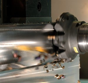
Milling non-ferrous materials
Non-ferrous materials includes not only aluminium, but also magnesium, copper and zinc based alloys. The machinability differs primarily depending on the Si-content. Hypo-euthectic aluminium is the most common type, with a Si-content below 13%.
Aluminium with Si-content below 13%
Material Classification: N1.1-3
The dominant wear criteria is built-up edge/smearing on the edges, leading to burr formation and surface finish problems. Good chip formation and chip evacuation are crucial for avoiding scratch marks on the component surface.
Recommendations
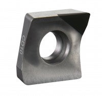
PCD-tipped insert
- Use PCD-tipped inserts with sharp and polished edge for good chip-breaking capabilities and built-up edge resistance
- Choose positive insert geometries with sharp edges
- Unlike most other milling applications, cutting fluid should always be used in aluminium to avoid smearing on the insert edges and to improve surface finish Si-content < 8%: Use cutting fluid with 5% concentration Si-content 8–12%: Use cutting fluid with 10% concentrationSi-content >12%: Use cutting fluid with 15% concentration
- A higher cutting speed generally improves the performance and does not negatively effect tool life
- A hex value of 0.10–0.20 mm (0.0039–0.0079 inch) is recommended. Values that are too low can lead to burr formation
Warning: Make sure that the maximum rpm for the cutter is not exceeded
- Due to the high table feeds, a machine with ”look-ahead” function should be used to avoid dimensional errors
- Tool life is always limited by the burr formation or surface finish on the component. Wear on the insert is difficult to use as a tool life criteria
Milling heat resistant superalloys (HRSA)
Heat resistant super alloys (HRSA) fall into three material groups; nickel-based, iron-based and cobalt-based alloys.Titanium can be pure or alloyed. The machinability of both HRSA and titanium is poor, especially in the aged condition, requiring particular demands on the cutting tools.
HRSA and titanium alloys
Milling HRSA and titanium often requires machines with high rigidity and high power and torque at low rpm. Notch wear and edge chipping are the most common wear types. The high heat generation limits the cutting speed.
Recommendations
Use round insert cutters to minimize notch wear
- Use round insert cutters whenever possible to increase the chip thinning effect
- For cutting depths below 5 mm (0.197 inch), the entering angle should be less than 45°. In practice, a round, positive-rake insert is recommended
- Cutter accuracy in both radial and axial directions is essential to maintain a constant tooth load and a smooth operation, and to prevent premature failure of individual cutter teeth
- The cutting edge geometry should always be positive with an optimized edge-rounding, to prevent chip adherence at the point where the edge exits the cut
- The number of cutting teeth actually in cut during the milling cycle should be as high as possible. This will provide good productivity if there is stability. Use extra close pitch cutters
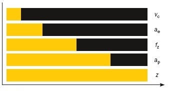

= Tool life

= Reduction in tool life as cutting parameter is increased
Changes have varying impacts on tool life; the cutting speed, vc, has the greatest impact, followed by ae, etc.
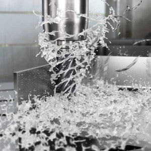
Cutting fluid/coolant
Unlike milling in most other materials, coolant is always recommended to assist in chip removal, to control heat at the cutting edge and to prevent the re-cutting of chips. High pressure coolant (70 bar (1015 psi)) applied through the spindle/tools is always to be preferred instead of an external supply and low pressure.
Exception: Cutting fluid should not be applied when milling with ceramic inserts due to the thermal shock.
Cutting fluid supplied through the cutters is advantageous when using carbide inserts
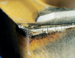
Insert/tool wear
The most common causes of tool failure and poor surface finishing are notch wear, excessive flank wear and edge line frittering.
The best practice is to index the cutting edges at frequent intervals, to ensure a reliable process. Flank wear around the cutting edge should not exceed 0.2 mm (0.0078 inch) for a cutter with a 90 degree entering angle, or a maximum of 0.3 mm (0.0118 inch) for round inserts.
Typical insert wear
Ceramic inserts cutter for roughing HRSA
Ceramic milling typically runs at 20 to 30 times the speed of carbide, although at lower feed rates (~0.1 mm/z (0.0039 in/z)), which results in high productivity gains. Due to intermittent cutting, it is a much cooler operation than turning. For this reason, speeds of 700–1000 m/min (2297–3280 ft/min) when milling are adapted, compared with 200–300 m/min (656–984 ft/min) for turning.
Recommendations
- Primarily use round inserts to ensure a low entering angle and to prevent notch wear
- Do not use cutting fluid/coolant
- Do not use ceramics when machining titanium
- Ceramics have a negative effect on the surface integrity and topography, and are therefore not used when machining close to the finished component shape
- Maximum flank wear when using ceramic inserts in HRSA is 0.6 mm (0.024 inch)
Read more about HRSA and titanium
Milling hardened steels
This group contains hardened and tempered steels with hardness >45–65 HRC.
Typical components being milled are:
- Tool steel inserts for stamping dies
- Plastic moulds
- Forging dies
- Die casting dies
- Fuel supply pumps
Abrasive flank wear on the insert and workpiece frittering are the main issues.
Recommendations
- Use positive insert geometries with sharp edges. This will reduce the cutting forces and produce a softer cutting action
- Run dry, avoid cutting fluid
- Trochoidal milling is a suitable method, which enables high table feeds in combination with low cutting forces, generating low cutting edge and workpiece temperatures which are beneficial for productivity, tool life and component tolerances
- The machining strategy to run light but fast should also be applied in face milling, i.e. small depths of cut, both ae and ap. Use an extra close pitch cutter and relatively high cutting speeds
วัสดุชิ้นงาน
Workpiece material groups The metal cutting industry produces an extremely wide... keyboard_arrow_right
CoroMill 216F
The CoroMill 216F cutter is used for finish milling of a range of materials used... keyboard_arrow_right
Turbine blade
Blade machining moves to a new level Competitive manufacturing blades for steam... keyboard_arrow_right
Turbine blade
Blade machining moves to a new level Competitive manufacturing blades for steam... keyboard_arrow_right
