
Milling inside corners
Milling inside corners requires careful considerations of the suitable arc of cutter engagement, as well as the appropriate feed rate.
Considerations
- When feeding the cutter into internal corners, the radial arc of engagement will increase and place extra demands on the cutting edge
- Often, the process becomes unstable, creating vibrations and an insecure process
- Wobbling cutting forces often create undercutting of the corner
- There is a risk for frittering the tool edges, or a total tool breakdown
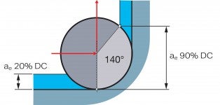
Traditional corner milling
Corner radius = 50% x DC
Solution – limit the arc of engagement
Use a programmed radius (circular milling) to reduce the arc of engagement and a radial cut to reduce the vibration tendencies, which will allow higher depths of cut and feed rates when milling inside corners.
- Mill a bigger corner radius than stated in the drawing. This can sometimes be favourable, as it allows the use of a bigger cutter diameter in roughing, which maintains high productivity
- Alternately use a smaller DC cutter to mill the desired corner radius
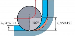
Mill a bigger component radius,
Corner radius = 75% x DC
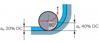
Use a smaller cutter,
Corner radius = 100% x DC
Roughing
A programmed radius of 50% DC is optimal.
Finishing
For finishing, it is not always possible to have such a large radius; however, the cutter diameter should be no larger than 1.5 x component radius, e.g. corner radius 10 mm (0.394 inch) = max 15 mm (0.591 inch).
Cutter path and chip formation
Correct cutter path and chip formation in milling are important factors to ensure... keyboard_arrow_right
Widening a hole
Widening an existing hole can be performed either by circular ramping or circular... keyboard_arrow_right
Vibration
Milling vibration can arise due to limitations in the cutting tool, the holding tool,... keyboard_arrow_right
Entering angle and chip thickness
The entering angle (KAPR) is the angle between the main, leading cutting edge of... keyboard_arrow_right
