
Entering angle and chip thickness in milling
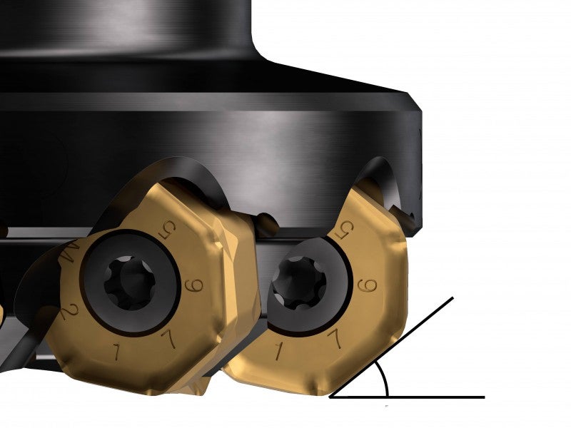
The entering angle (KAPR) is the angle between the main, leading cutting edge of the insert and the workpiece surface. The entering angle affects chip thickness, cutting forces and tool life.
The most common entering angles are 90 degree, 45 degree 10 degree and those of round inserts.
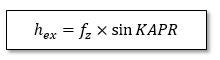
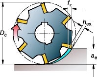
When decreasing the entering angle, the chip thickness, hex, reduces for a given feed rate, fz. This chip thinning effect spreads the amount of material over a larger part of the cutting edge.
Smaller entering angles also provide a more gradual entry into the cut, reducing radial pressure and protecting the cutting edge. However, the higher axial forces increases the pressure on the workpiece.
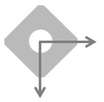
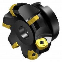
Milling with 90 degree entering angle
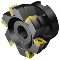
The main application area for a 90 degree cutter is square shoulder milling.
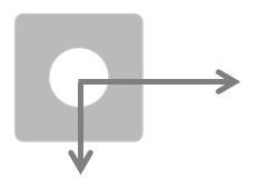
A 90 degree cutter generates mostly radial forces, in direction of the feed. This means that the surface being machined will not be exposed to high axial pressure, which is advantageous for milling workpieces with a weak structure or thin walls, and in cases of unstable fixture.
Milling with 45 degree entering angle
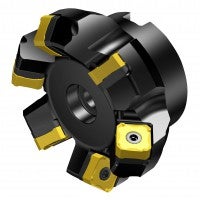
A 45 degree cutter is the general purpose choice for face milling. It generates well balanced radial and axial cutting forces which is less demanding on the machine power.
This type of cutter is especially suitable for milling in short-chipping materials that easily fritter if excessive radial forces act on the gradually reduced amount of material left at the end of a cut.
The smooth entry into cut limits vibration tendencies when milling with long overhangs or with smaller/weaker tool holders and couplings.
The formation of a thinner chip allows for high productivity in many applications, because of the opportunity for higher table feed while maintaining a moderate cutting edge load.
Milling with 60–75 degree entering angle
These type of cutters are special purpose face mills offering larger depth of cut compared to the general choice face mills. The axial forces are lower compared to a 45 degree face mill cutter and the edge strength is better compared to a 90 degree cutter.
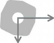
Milling with 10 degree entering angle
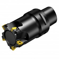

A 10 degree entering angle is used on high-feed and plunge milling cutters. A thin chip is generated that allows for very high feeds per tooth, fz, at small depths of cut and, consequently, for extreme table feeds, vf.
The dominating axial cutting force is directed towards the spindle and stabilizes it. This is favorable for long and weak set-ups, as it limits vibration tendencies.
This type of cutter is effective in hole making when using three axes and for plunge milling of cavities, or whenever use of an extended cutter is required.
Milling with round inserts or cutters with a large corner radius

A round insert cutter is for general purpose milling and is efficient for roughing operations.
The corner radius provides a very strong cutting edge, suitable for high table feed rates because of the thinner chips generated along the long cutting edge. The chip-thinning effect makes these cutters suitable for machining titanium and heat resistant alloys.
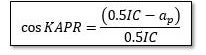
Depending on cutting depth variations, ap, the entering angle changes from zero up to 90 degrees, altering the cutting force direction along the edge radius, and consequently the resulting pressure during the milling operation.
Maximum chip thickness in milling
Maximum chip thickness is the most important parameter for achieving a productive and reliable milling process. Effective cutting will only take place when the hex value is correctly matched to the milling cutter in use.
- A thin chip with a hex value that is too low, is the most common cause of poor performance resulting in low productivity. This can negatively affect tool life and chip formation
- A hex value that is too high will overload the cutting edge, which can lead to breakage
Chip thinning allows for increased feed
Feed per tooth can be increased in the three following situations due to the chip thinning effect:
- Using straight edge cutters with entering angles lower than 90°.
- Using round inserts or large radius inserts, at smaller depths of cut, ap.
- Peripheral milling at a small radial engagement, ae/De.
Chip thickness calculations for straight edge insert
With 90 degree cutters the feed per tooth equals the maximum chip thickness (fz=hex). When decreasing the entering angle, increase feed per tooth to make sure to keep the same chip thickness.
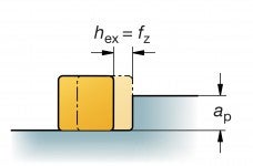
KAPR=90°
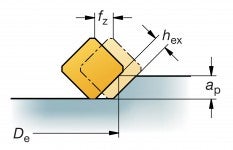
KAPR=45°
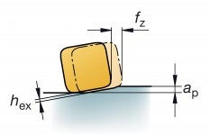
KAPR=10°
Example:
If maximum hex = 0.1 mm and KAPR = 45°
Recommended feed, fz = 1.4 x 0.1 = 0.14 mm/tooth
| Entering angle, KAPR | Modification factor | fz (mm/tooth) | ||
| hex (mm) | ||||
| min. 0.1 | start 0.15 | max. 0.2 | ||
| 90° | 1.0 | 0.10 | 0.15 | 0.20 |
| 75° | 1.0 | 0.10 | 0.16 | 0.21 |
| 65° | 1.1 | 0.11 | 0.17 | 0.22 |
| 45° | 1.4 | 0.14 | 0.21 | 0.28 |
| 10° | 5.8 | 0.58 | 0.86 | 1.15 |
Watch how much you can increase feed per tooth on the high feed, 10 degree cutter. This is because you are thinning the chip out by a factor of almost six times.
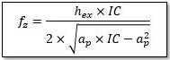
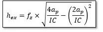
Chip thickness calculations for round and radius insert cutters
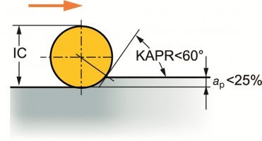
The chip thickness, hex, varies with round inserts, and depends on the entering angle. With low ap/i C ratios, the feed can be increased considerably in order to raise the chip thickness to a desired level.
Best performance is achieved when the entering angle remains under 60 degrees and with a depth of cut that not exceeds 25% x insert diameter. For larger depth of cuts it is more beneficial to use a 45 degree square insert.
Round inserts have a higher maximum chip thickness capability than straight edge solutions, due to the stronger insert shape and longer cutting length.
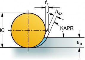
Round inserts are unique in that the chip thickness changes based on the depth of cut. Therefore, at lower depths of cut you need to increase your feed to be sure to obtain the proper chip thickness.
Chip thickness calculations for peripheral milling
The hex value varies depending on the cutter diameter and working engagement, the radial immersion of a cutter, ae/DC. When this is smaller than 50%, maximum chip thickness is reduced relative to fz.
Feed can be increased by the modification value in the table below depending on the ratio, ae/DC.Example:
DC 20 mm – ae = 2 mm, ae/DC = 10%
hex = 0.1 mm, fz = 0.17 mm/tooth
| Width of cut diameter ratio, ae/DC | Modification factor | fz (mm/tooth): | ||
| hex (mm) | ||||
| min. 0.1 | start 0.15 | max. 0.2 | ||
| 50-100% | 1.0 | 0.10 | 0.15 | 0.20 |
| 25% | 1.16 | 0.12 | 0.17 | 0.23 |
| 20% | 1.25 | 0.13 | 0.19 | 0.25 |
| 15% | 1.4 | 0.14 | 0.21 | 0.28 |
| 10% | 1.66 | 0.17 | 0.25 | 0.33 |
| 5% | 2.3 | 0.23 | 0.34 | 0.46 |
Cutter path and chip formation
Correct cutter path and chip formation in milling are important factors to ensure... keyboard_arrow_right
วิธีในการเลือกเม็ดมีดกลึงที่เหมาะสม
การเลอกเมดมดมกลงตองคำนงถงหลายสง ทงการเลอกหนาลายเมดมด เกรดเมดมด รปทรงของเมดมด (มมปลายตด)... keyboard_arrow_right
Milling inside corners
Milling inside corners requires careful considerations of the suitable arc of cutter... keyboard_arrow_right
Down milling vs. up milling
Each time a milling edge enters a cut, it is subjected to a shock load. The right... keyboard_arrow_right
