Boring
Product overview
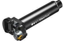
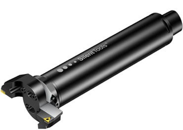
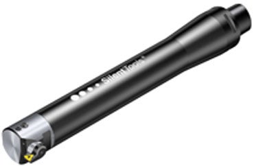
Sandvik Coromant offers dampened boring tools for rough and finish boring. The adapters are designed with Coromant Capto backend couplings for best possible clamping and flexibility. This gives you unique flexibility and modularity to build desired tool assemblies. Coromant Capto basic holders are available in all common machine interfaces.
Silent Tools finish and rough boring tools give increased productivity and close tolerances from lengths of 3–10 x BD. When using Silent Tools, you have the opportunity to double the depth of cut. Through coolant is a feature for precise direction of jets to the cutting zone.
Using extension and reduction adaptors are possible on damened boring tools, but the tool will no longer be optimized. However, a dampened tool with extension or reduction still performs better than an undampened tool.
Boring bar adaptor dia, DC
inch
mm
| Engineered products |
CoroBore 825 ® Integrated dampened boring tool 825 with 1 insert Coromant Capto |
DuoBore ™ Integrated dampened boring tool with 2 inserts Coromant Capto |
| Rough boring | Fine boring | |
Boring range Ø 25-150 mm (0.984-5.906 inch) | Boring range Ø 23-167 mm (0.906-6.575 inch) | Boring range Ø 150-315 mm (5.906-12.402 inch ) |
Dampened DuoBore
™ |
Dampened CoroBore
® 825 | |
 |  |  |
| Coromant Capto® back-end coupling Coolant through |
 |
| 6 x DC (23.6–27.6 inch) |
| IT9 |
| Internal |
| 90°(0°) CoroTurn 107°, 75°(15°) CoroTurn 107° |
 |
| 6 x BD |
| IT9 |
| Internal |
| 0.002 mm (0.000079 inch) |
| 92° (-2) CoroTurn 107°, 92° (-2) CoroTurn 111° |
Radial adjustment of fine boring head:
|  |
®How to use CoroBore 825
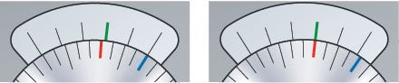
| Example of setting: In this example the blue line on the scale disc is a reference since it is aligned to a line on the vernier in the starting position. | 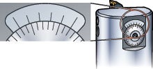 |
| Start position | Adjusted position |
 | |
Scale disc turned clockwise until the line of scale (red) lines up with the second line (green) of the vernier. Diameter increased by 0.002 mm (0.00008“) | |
 | |
Scale disc turned clockwise until the line of scale (red) lines up with the third line (green) of the vernier. Diameter increased by 0.004 mm (0.00016“) | |
 | |
Scale disc turned clockwise until the line of scale (red) lines up with the fourth line (green) of the vernier. Diameter increased by 0.006 mm (0.00024“) | |
 | |
Scale disc turned clockwise until the line of scale (red) lines up with the fifth line (green) of the vernier. Diameter increased by 0.008 mm (0.00032“) | |
 | |
Scale disc turned clockwise until the line of scale (red) lines up with the sixth line (green) of the vernier. Diameter increased by 0.010 mm (0.0004“) = 1 division of scale. |
Main considerations
The Silent Tools boring tools reach a maximum of six times the bore diameter into your workpiece. If you need to go deeper, ask for an engineered solution.
Our recommendation is to always use Silent Tools for long overhangs, over 4 x BD.
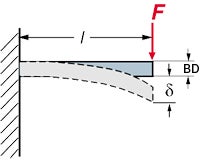
Tool overhang and diameter of tool
|  |
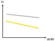 |   | -PR - WM | 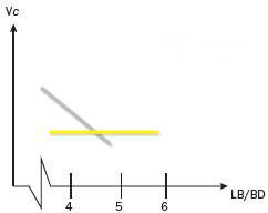 | | Conventional Dampened adaptor |
| Cutting speed in relation to overhang, with different geometries | Cutting speed in relation to overhang, with conventional and dampened adaptors |
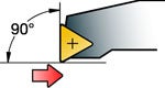
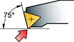
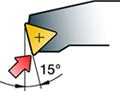
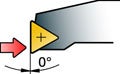
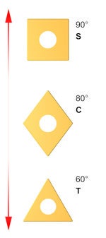
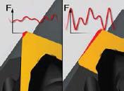
Insert shape and entering angle/lead angle
Use entering angle 90° (0°) for roughing and 92° (-2°) for finishing. Less force in the radial direction gives less radial deflection and vibration. Triangular-shaped inserts (T-style) are first choice for boring operations. CoroTurn® 107 inserts meet these requirements and are first choice.
Nose radius
The nose radius, RE, on the insert is a key factor in turning operations. Selection of nose radius depends on the:
- Depth of cut, ap
- Feed, fn
and influences the:
- Surface finish
- Chip breaking
- Insert strength
Small nose radius
- Ideal for small cutting depths
- Reduces vibration
- Less insert strength
Large nose radius
- Heavy feed rates
- Large depths of cut
- Stronger edge
- Increased radial forces
Nose radius in relation to depth of cut
The radial forces that push the insert away from the cutting surface become more axial as the depth of cut increases. The nose radius also affects the chip formation. Generally, chip breaking improves with a smaller radius. As a general rule of thumb, the depth of cut should be greater than or equal to 2/3 of the nose radius or half the nose radius in the feed direction.
Feed starting values depending on nose radius
| 0.4 (0.016) | 0.8 (0.031) | 1.2 (0.047) |
| 0.17 (0.007) | 0.22 (0.009) | 0.27 (0.011) |
 |  |
 |  |
| Force direction mainly axial | Force direction both axial and radial |
Rough boring
Productive boring
| Involves two cutting edges and is employed for roughing operations of holes, with tolerance IT9 or larger, where metal removal rate is the first priority. Feed rate is obtained by multiplying the feed by the number of inserts. (fn=fz x ZEFF) | 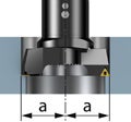 Productive boring |
Step boring
| When adding a shim under one of the slides, the insert will only take the inner half of the desired radial cut, and the result is a stepboring tool. Select this method if you want to take a larger radial cut than one insert can take, but remember to reduce the axial feed to what is normal for a tool with only one cutting edge. If the two inserts are set to take the same radial depth of cut, the outer one will always take the largest cutting force, due to higher speed and more chip removal. By doing this right, vibration can easily be avoided and a smooth surface is guaranteed. This set-up will produce a stepped shoulder if it is not going through the workpiece. The feed rate and the produced surface finish is the same as if only one insert is used (fn=fz). Produced hole tolerance is IT9 or larger. | 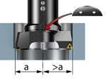 Step boring |
Single-edge boring
Single-edge boring is the best option when:
Produced hole tolerance is IT9 or larger. | 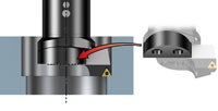 Single edge boring |
Finish boring
Factors that influence vibration
To reduce vibrations, choose a light cutting insert with a positive cutting geometry and small nose radius. T-style inserts are first choice for boring operations.
| High vibration tendency | – Heavy feeds – Large depth of cut – Strong edge security |
 |  |
| Less vibration tendency | – Ideal for small depth of cut – Reduces vibration |
Information about other vibration influence factors such as the following can be found in the application guide, read more.
- Insert point angle
- Positive geometries
- Wiper inserts
- Edge rounding
- Cutting data and cutting speed.
Tips and tricks
- Choose the largest possible tool diameter with the shortest possible basic holder
- The entering angle should be close to 90 degrees to give more axial cutting forces and less radial/tangential forces
- A small nose radius is ideal for small depths of cut and decreases the risk of vibrations. Large nose radii have strong edge security and allow for heavy feeds and large depths of cut. The risk of vibration gets higher the larger nose radius you use. Therefore, triangular, positive style inserts are first choice for dampened boring operations
- In stable conditions, use wiper inserts for high productivity or when high quality surfaces are required
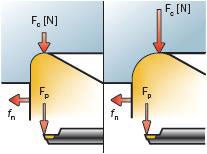 | | |
 | Conventional | |
| Dampened adaptor | |
| Less radial forces (Fc) with small radii |
with conventional and dampened adaptors |
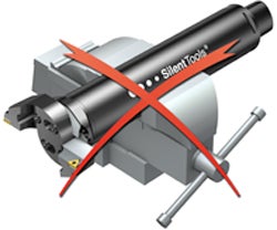
Tool assembly and maintenanceWhen using dampened tools in assemblies, care should be taken to hold the tool bodies correctly to make sure that the adaptors are not damaged. These are easily deformed due to the thin wall thickness.
| 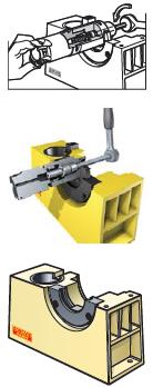 |