Milling
Product overview
There is a wide range of Silent Tools milling adaptors available off the shelf, with HSK or modular Coromant Capto couplings. If none of our standard adapters are suitable, inquire for an engineered solution. Adaptors for slitting cutters, built-in dampeners in large side mills and long-edge cutters are also available as engineered solutions.
End mills and square shoulder face mills | Dampened adaptors for face mills and square shoulder face mills | |
| ® CoroMill390D | Dampened adaptors | Dampened adaptors – HSK |
 |  |  |
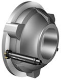
Cylindrical shank or Coromant Capto back-end coupling | Coromant Capto back-end coupling (C4, C5, C6 and C8) | HSK back-end coupling (HSK 63 and HSK 100) |
Coarse, close and extra close pitch | Wide range of exchangeble cutting heads | Wide range of exchangeble cutting heads |
DC: 20-40 mm (0.787-1.575 inch) | Coolant through | Coolant through |
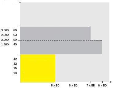
| Overhang: ≤ 5 x BD | BD: 40-80 mm (1.968-3.150 inch) | BD: 63-100 mm (2.480-3.937 inch) |
DMM: 16-32 mm (0.750-1.500 inch) | DMM: 16-27 mm (0.750-1.000 inch) | |
| Overhang: ≤ 8 x BD | Overhang: ≤ 8 x BD |
- Dampened solutions from 20–40 mm (0.79–1.57 inch) with integrated CoroMill 390 milling cutters are available in the standard assortment
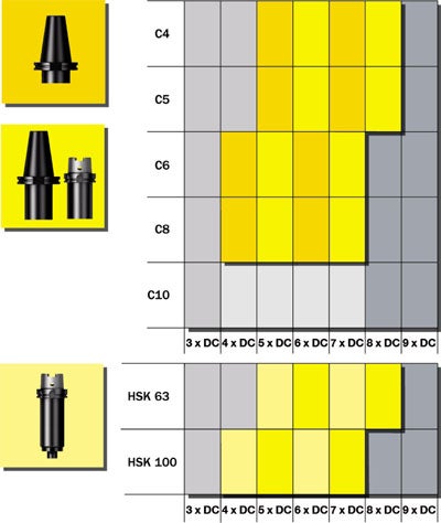
- From 40 mm (1.57 inch) and above, there are dampened adaptors with Coromant Capto sizes C4–C8, with coolant through arbor mounting available as standard. Combined with a basic holder, the adaptor can be an assembled dampened tool for most machine interfaces
- For machines with HSK couplings; integrated adaptors are available with a possibility to assemble with Sandvik Coromant HSK basic holders
- MSSC holders adaptors are also available in the stardard program
| Adapter dia, BD | |||
| inch | mm | ||
 | Overhang LU/BD |
 | Engineered products |
 | Coromant Capto® & HSK adaptors for rotating tools Dampened adaptor for face mills and square shoulder face mills |
 | CoroMill® 390D End mill and square shoulder face mill |
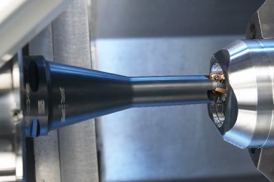
CoroMill® 390D – application area
CoroMill 390D is a real productivity booster for long and slender tools and works well in both vertical and horizontal machines. The cutters are designed for reach and at the same time efficient when machining close to chucks in multi-task machines.
The program consists of Coromant Capto sizes C6, C5 and cylindrical shanks in diameter 20, 25 and 32 mm (0.79, 0.94 and 1.26 inch) with a reach of 3–5 times the cutting diameter, DC.
- High stability
- Large programme of basic holders
- First choice for closed reach
- High stability
- Large programme of basic holders
- Integrated multi-task spindles
- First choice for open reach
- Coromant Capto® C5
- Coromant Capto® C6
- Cylindrical shanks
- CoroChuck™ 930 for accurate holding of the cutter
- Collet chucks
Short and long basic holders
With a combination of arbor mounting on the adaptors and basic holders with different lengths, solutions for most applications up to 8 x BD are available. For overhangs above 8 x BD, or when you have other specific requirements, engineered solutions are the best alternative.
| Undampened/Solid | 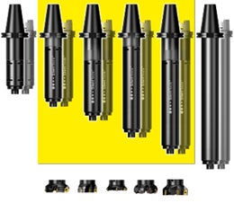 |
Engineered solution |
Dampened adaptors for face mills and square shoulder face mills
- Cx-391.05CD
- 392.41005CD
Main considerations
Working with rotating tools differ from turning, where you have a boring bar in a rigid tool post, but most of the conditions for successful operations are the same:
|  |
Reduce vibration
Workpiece set up and machine stability are two important things to consider carefully to minimize vibration.
Workpiece
- Affix the workpiece in the most favourable way to support the cutting forces which arise during the machining process
- Use milling concepts with design and entering angle that generate cutting forces in the most stable direction of the workpiece
- Optimize the machining strategy and direction to obtain the most stable cutting condition as possible
Machine
- Machine condition have a large influence on vibration. Excessive wear of the spindle bearing or feed mechanism will result in poor machining properties.
All Silent Tools dampened adaptors are designed for different overhangs, and with differently tuned dampers. The best performance will be achieved by using the optimized length instead of adding extension adaptors. If there is a need for more than 7–8 x BD, ask for an engineered adaptor.
| Damping effect | |
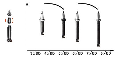 | |
| Less damping effects with extensions! | Use damped adaptors for its optimized area! |
Programming guidelines
A general rule for face milling is to keep the milling cutter constantly in cut, instead of running several length way passes. This minimizes the number of entries and exits and keeps the inserts from disadvantageous loads that could lead to vibration.
 |  |
| Roll into cut | Keep the cutter constantly engaged |
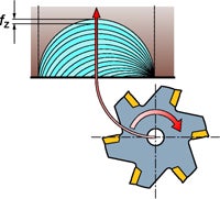
Roll into cut
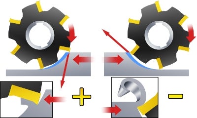
Roll into the cut clockwise to get thin chips, approaching zero at the exit. This approach will avoid vibration tendencies that can originate from a
thick-chip-at-exit approach.
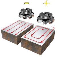
Milling direction
Down-milling is the first choice for most milling operations. In some cases, when the machine has insufficient power or the workpiece is very pliable, up-milling is preferred. Remember however that the cutting force tends to lift the workpiece when up-milling. This must be carefully counteracted when clamping the workpiece.
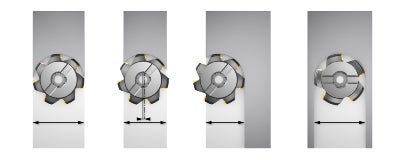
Position and diameter
In general face milling, the cutter diameter should be 20-50% larger than the cutting width and the cutter should be positioned slightly off-centre. Do not position the cutter exactly in the centre.
When the cutter diameter is smaller than the workpiece, it is recommended that maximum width of cut is 60-70% of the cutter diameter.
In full slot milling, it is very important to reduce the number of engaged inserts to avoid vibration.
Factors that influence vibration
There are four basic factors that have a major influence on vibration:
- Entering/lead angle and cutting forces
- Cutter diameter relative to radial depth of cut
- Insert geometry
- Cutter pitch
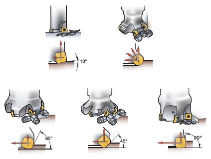
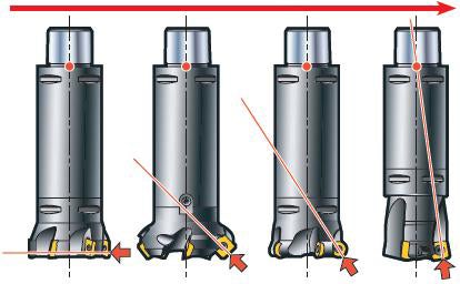
Entering angle
The entering angle is important as it determines the direction of the cutting forces. The larger the kappa angle (KAPR), the larger the radial cutting forces. Choose cutter concept according to process and application.
When the radial cutting forces increase, you can see the difference in functionality between dampened and undampened tools.
With a small entering angle combined with shorter overhang, the maximum depth of cut on the cutter could be reached before vibration occure.
Increased tool stability | |||
 | |||
| CoroMill 345 | CoroMill 210 |
Cutter diameter relative to radial depth of cut
A smaller tool diameter will reduce the power and torque requirements as well as the deflective cutting forces. The ratio of the milling cutter diameter in relation to the radial engagement needs to be kept smaller than any maximum value.
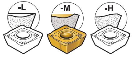
Insert geometry
The cutting tool geometry should be light or medium.
Silent tools limits
High temperatures can change the function of the dampening system. Use air or through coolant when possible. Extreme n (rpm) can also reduce the function of the dampening system.
Cutter pitch
When multiple inserts are in contact with the material, the risk of vibration increases. As long as you are working with cutting depths under the critical depth for vibration, an increased number of inserts is more productive however. Work with both radial engagement and the pitch of the cutter to find the best performance. In most cases a coarse pitch is the best choice for productive machining with dampened tools.
Differentially pitched cutterHarmonic forces cause vibration and a differentially pitched cutter is therefore an effective way to minimize vibration. It breaks the harmonic forces and therefore increases stability and is especially useful when ae is high and and you have long overhangs. | 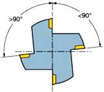 |
| Coarse pitch -L | Close pitch -M | Extra close pitch -H | ||
 |  |  | ||
| Differentially pitched cutter with reduced number of inserts. First choice for unstable operations due to the lowest cutting forces. | Evenly or differentially pitched cutter, depending on concept, with medium number of inserts. First choice for roughing in stable conditions. | Evenly pitched cutter with maximum number of inserts. First choice for high productivity with low ae (more than one edge in contact). |
Tips and hints
Insert grades and geometries
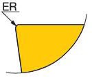
Choose a small edge rounding (ER). Go from thick coating to a thin one. If necessary, use uncoated inserts. Use sharp and positive inserts with chip forming capacity.
Entering angle
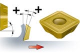
The smaller the entering angle, the thinner the chip, and the further away it will spread along the cutting edge. This allows for higher feed per tooth. A smaller entering angle will also direct more of the cutting force in axial direction and reduce the risk of vibration.
Cutter pitch
In most cases a coarse pitch is the best choice for productive machining with dampened tools. Use a coarse pitch cutter to slow down changes in the cutting force directions. Reducing the number of inserts will often enable a significant increase in the axial depth of cut.
Feed per tooth
A higher feed per tooth may give a constant preload on the machine tool spindle and prevent it from using the play in its bearings.
Achieve maximum Q
Choose ae between 60%–80% as a starting value if possible. Reduce the number of inserts to maximize Q. This is particularly important when using full slot engagement.
Chip evacuation
Use compressed air to prevent re-cutting of the chips. This is especially important in deep-cavity milling. Notice that a coarse pitch cutter will have more space to evacuate the cips.
Entry and exit
Avoid situations where the centre line or the cutter is in line with the workpiece edge. In situations like that, the insert is leaving cut when the chip thickness is at its maximum, which gives very high shock-loads at entry and exit.