
Face grooving

When making an axial groove on the face of a component it is important to choose the correct tools. The bending radius of the groove will determine the curve of the tool. Chip evacuation can be a problem in face grooving due to the curved groove. Chips jamming in the groove can lead to insert breakage, which jeopardizes process security.
How to choose the correct face grooving tools
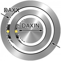
Diameter range (DAXIN and DAXX)
Choose the diameter range of the first cut (DAXIN and DAXX). Use the tool for the largest diameter that fits your groove. A tool for a larger diameter is less curved and hence more stiff and stable. It also gives improved chip control.
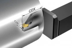
Cutting depth (CDX)
Always use a tool with shortest possible cutting depth (CDX) to have maximum stability.
Insert width (CW)
Use the widest insert and tool that can be used for your groove. A wider holder has higher stiffness and gives more stability.
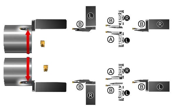
Hand of tool and type of curve
Choose the correct tool (A- or B-curve, right- or left-hand style) depending on your machine set-up and workpiece rotation
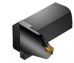
- A-curve = for internal machining
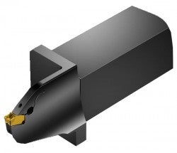
- B-curve = for face grooving to Boss
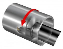
A curve
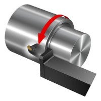
B curve
Tool holder recommendation
Depending on the face grooving operation, when choosing the correct tool holder you need to consider the following:
- Choice of machine interface. Choose between a modular or solid solution, such as QS shank
- 0° or 90° holder
- Right or left hand tool. This depends on your previous choices
0° holder
90° holder
Right or left hand?
See if you need right or left hand tool depending on your previous choices.
For best results in face grooving, it is recommended to use a system specifically designed for this operation such as CoroCut QF. For more guidance on how to choose the correct face grooving tool go to the specific product page, or use CoroPlus® ToolGuide
Tailor made tools
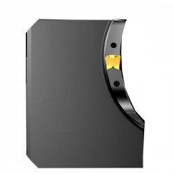
All standard face grooving tools are designed to cover a range of diameters of first cut. To get an optimized tool for the groove to machine, the option is to invest in a Tailor Made tool holder. This blade is tailored for a certain first cut diameter and has an even shape, which is stiffer compared to the standard comma shaped blade (see image). The cutting depth and first cut diameter can be set exactly the way you need, giving an optimized tool for face grooving.
Standard holder
Higher tool stiffness
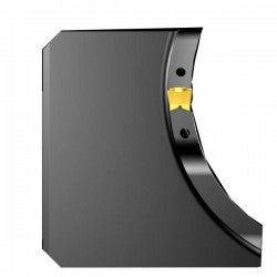
Tailor made holder
How to choose the correct face grooving tools when boring
When making an axial groove in a component, it is important to choose correct tool holder for the insert. The tool holder must be adapted to the bending radius of the groove and should therefore be curved. Chip control is essential in face grooving, the chip should be long enough not to get stuck in the groove, but short enough not to get stuck around tool or component.
Face grooving operations
Strategies
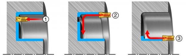
Roughing
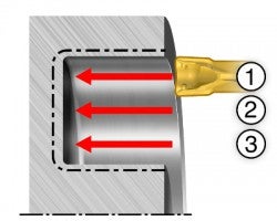
Always start on the largest diameter (1) and work inwards. Continuous chip is preferred at this step to avoid chip jamming in the narrow groove. Use pecking or micro stops if you need to have shorter chips. Further cuts (2, 3) should be 0.5 ‒ 0.8 × insert width. Since it is easier for chips to come out at this point, you can increase the feed by 30‒50%. Usually, you get shorter chips at this steps.
Deep grooves
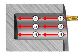
When machining deep grooves (>25 mm (0.984 inch)), it is recommended to do it in two steps:
- Machine a groove with 50% depth and required width (1, 2, 3)
- Machine to the required depth(4, 5, 6)
Roughing with side turning
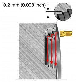
p
Side turning provides better chip control and chip breaking. Start on the largest diameter and machine towards the centre. Do not feed from and against shoulder, leave 0.2 mm (0.008 inch) steps between the passes. Side turning is a more stable process than cutting with axial feed. Use side turning to avoid vibration. Be aware that side turning is less productive than axial cuts due to lower depth of cut (a)
Finishing
It is always tricky to achieve good chip control when finishing, especially when it comes to machining of fillets. It is important to separate the material to be removed by producing three cuts.
- Make a first axial cut close to the corner radius on the largest diameter
- Start the second cut on the largest diameter and machine to the corner radius on the inner diameter
- The third cut finishes the inner diameter and the corner radius
Precision coolant
Use face grooving tools with precision coolant supply even if the maximum coolant pressure in your machine is low (7‒10 bar (102‒145 PSI)). Precision coolant improves chip evacuation and decreases risk for chip jamming in the groove, especially in deeper grooves. Use as high coolant pressure as possible, up to 80 bar (1160 PSI), to achieve better chip control and chip evacuation.
Internal grooving
Long overhangs and poor chip evacuation are two of the challenges with internal grooving.... chevron_right
External grooving
For grooving, high productivity is the goal. External grooving is generally less... chevron_right
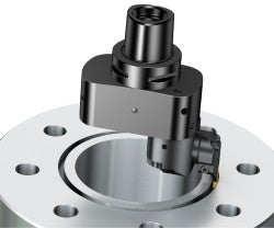
CoroBore 825 SL face grooving
Machining grooves with CoroBore SL is a productive alternative to milling grooves.... chevron_right
How to achieve good component quality in turning
To achieve quality turned components, chip control is one of the most important factors... chevron_right
