
CoroCut® QF
Secure face grooving
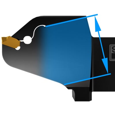
Innovative blade design
More material in the weakest cross-section and decreased mass in the front part of the blade provide higher dynamic stiffness, effectively reducing vibration. The slit is optimized to provide correct clamping force.
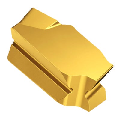
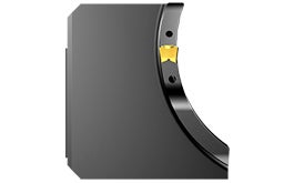
Insert design optimized for stable face grooving
Tilted insert with stabilizing rails at the top, bottom and back of the insert to minimize insert movement.
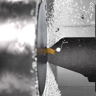
Precision coolant supply
Improves chip evacuation and decreases the risk for chip jamming, critical factors for successful deep face grooving operations. Effective from low to high coolant pressures.
Application
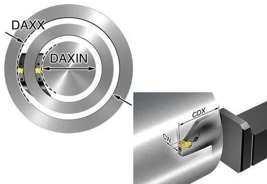
- Face grooving
- Minimum first cut diameter (DAXIN): 30 mm (1.18 inch)
- Maximum cutting depth (CDX): 50 mm (1.97 inch)
- Minimum corner radius: 0.2 mm (0.008 inch)
Product range
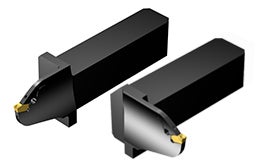
QS™ shanks
Metric size 25×25
Inch size 1×1
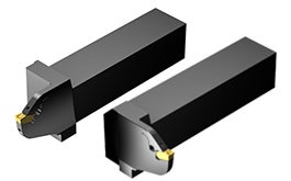
Shanks
Metric size 32×32
Inch size 1×1
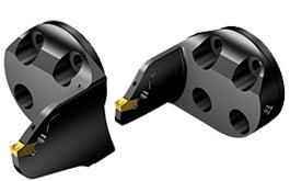
CoroTurn® SL heads
Size 32 and 40
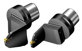
Coromant Capto®
Size C5, C6 and C8
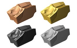
Inserts
- CW 3, 4, 6 and 8 mm (0.118, 0.157, 0.236 and 0.315 inch)
- Grade GC1105, GC1125, GC1135, GC1145, H10F
- -TF geometry for grooving and side turning
- -GF ground geometry for grooving
- -RM geometry for profiling
Tailor Made
Build an optimized tool with the exact cutting depth and diameter range required for your component.
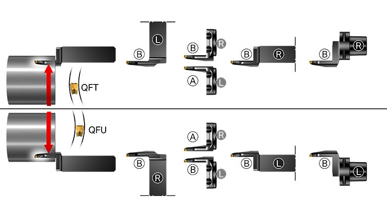
Tool selection
There are a number of important aspects to consider when choosing the right face grooving tool for your operation, such as clockwise or counter clockwise spindle rotation, A- or B-curve and right- or left hand tool. Use the step-by-step guide to facilitate your tool selection.How to use
Highlights
Demo: CoroCut® QF
CoroCut® QF is designed for face grooving, delivering unmatched reliability and superior process security.
Demo: Non-linear turning with CoroCut® QF
Non-linear tool path profiling distributes wear along the cutting edge to maximize tool life. The method ensures good chip control and chip breaking.
Get to know CoroCut® QF
Learn more about all the features that make CoroCut® QF first choice for face grooving.
Join us. Stay updated.
Sign up for our newsletter today

Sandvik Coromant UK
+44 (0)121 368 0305