
Fundamentals
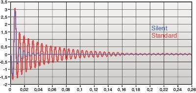
Inside a dampened tool is a pre-tuned dampening system that consists of a heavy mass, supported by rubber spring elements. Oil is added to increase the dampening.
The graph shows the difference in vibration dampening between an undampened and a dampened solution.
For long tool overhang and flanges, two-face contact between the spindle and the tool holder is recommended.
Two face contact |
Single face contact | 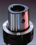 Coromant Capto coupling | |
Coromant Capto |  | ISO/CAT |  |
| BIG PLUS |  | MAS BT |  |
| HSK |  | CAT-V |  |
It is important to respect the limits marked on the product (load, temperature, rotation, min/ max overhang and pressure):
- Temperature is highlighted to save the rubber elements in the dampening system
- Maximum temperature limit depends on type of product and is marked on the tool, eg. 75-120°C (167-248 F)
The dampening system consists of a heavy mass, supported on rubber spring elements. | ||
Dampening system inside tool body • Heavy metal body • Pre-tuned • High reliability | 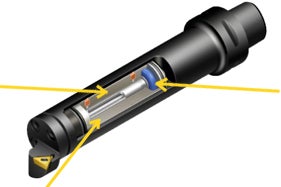 | Rubber springs |
| Oil is added to increase the dampening |
Reduce the cutting forces
Start out by choosing the best available cutting solution. Then, choose the largest possible diameter and shortest possible overhang to minimize deflection.
The next thing to have in mind is that the dampening system should be as close to the cutting edge as possible, and that the weight in front of the damper should be as light as possible. Reduced weight on the cutting tool will minimize the kinetic energy in a potential vibration. This will make it easier for the tool to dampen vibration, and thus stretch the maximum overhang for both solid and damped tools.
By implementing these strategies, you will reduce the force variations and vibration.
| Deflection (δ) = 64FLU3/3E(π)BD4 | 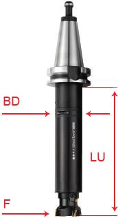 |
E: F: LU: BD: | Young's modulus Force Usable length Body diameter |
In summary:
- Reduce cutting forces by choosing the right cutting tool and insert
- Minimize deflection by increasing the static stiffness through largest possible shank diameter and minumum length
- Reduced weight on cutting units will minimize the kinetic energy in a potential vibration
- When extending modular tools, build large diameters
- For engineered products, consider optimized shapes and material reinforcements
Mechanical structures tend to vibrate with one or more resonance frequencies determined by geometry and material. Each resonance frequency corresponds to a ”vibration mode”. The dampening determines how fast the vibration settles after being triggered. With increased deflection, the energy in the oscillation increases. The force variations in machining will trigger the self-induced vibration at the natural frequencies of the machine tool. Once the vibration is triggered, it will feed on the forced vibration and grow larger and larger, unless you can reduce the force variations. Variations in machining forces can depend on a number of things, and if nothing is done to reduce the cutting forces, the vibration will increase. - Chip segmenting process - Interrupted cut - Inclusions in the material - Ovality in the workpiece - Formation of built-up edge k = spring constant m = object mass f = vibration frequenzy δ = tool deflection F = force on the tool  |
