
Turning
Product overview
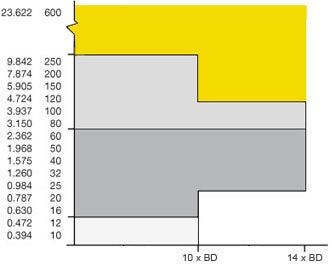
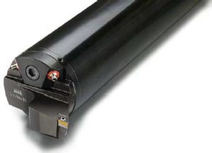
Selection of boring bar has a big impact on production economy. The Sandvik Coromant tool program is comprehensive and covers solutions from diameter 10 to 250 millimeter (0.40 to 9.84 inch) as standard off-the-shelf tools that will be delivered within 24 hours. Outside that range, engineered tools up to diameter 600 millimeter (23.6 inch) are available.
Overhangs 3–14 x BD bars are available while for Coromant Capto, you will find sizes from diameter 16 to 100 millimeter (0.63 to 3.94 inch).
Productive for short overhangs
Generally, you can use a steel or carbide boring bar for overhangs up to 4 x BD, but even in this range, a Silent Tools bar will give you very productive advantages. Overhangs up to 10 x BD are usually solved by applying a steel dampened boring bar to accomplish a sufficient process, while overhangs over 10 x BD require a carbide reinforced dampened boring bar to deal with radial deflection and vibration.
| Boring bar diameter, DMM | ||||
| inch | ||||
 |   | |||
| Max. overhang | ||||
Steel dampened boring bars | Carbide reinforced dampened boring bars |
 | Engineered products | |
 | CoroTurn® SL – QC | |
 | CoroTurn® SL | |
 | Integrated |
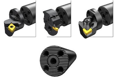
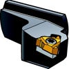
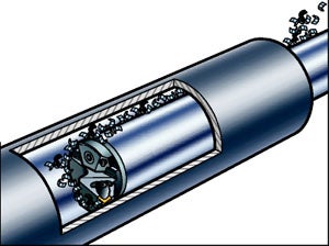
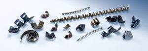
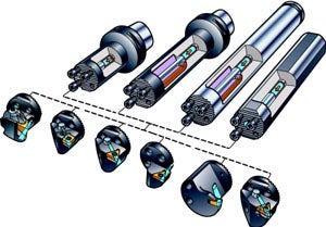
If you work with a combination of cutting heads and Silent Tools dampened boring bars, you can easily change only the head if there is damage on the tip seat.
There is a comprehensive offer of around 500 different cutting heads available for general turning, parting & grooving and threading, including Quick Change QS in diameter 32 and 80 mm (1.26 and 3.15 inch). There is also a dedicated program of CoroTurn HP cutting heads available.
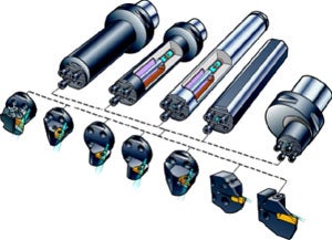
A combination of cutting heads and Silent Tools dampened boring bars gives great flexibility, with cutting heads for different applications.
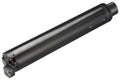
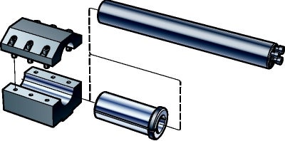
Large cylindrical boring bars come in several different couplings, such as Coromant Capto and Quick Change coupling units.
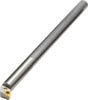
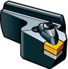
CoroTurn® SL
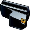
Quick Change QS
 |  |
 | |
 |
Bar types
Internal turning is very sensitive to vibration. Minimize the tool overhang and select the largest possible tool size in order to obtain the best possible stability and accuracy. For internal turning with steel dampened boring bars, the first choice is bars of type 570-3C.
For grooving and rough threading operations where the radial forces are higher than in turning, the recommended bar type is 570-4C.
The table below shows the maximum recommended overhang for different bar types.
The static stiffness of a carbide reinforced bar is improved by about 2.5 times compared to a steel bar with the same overhang.
There are different dampening systems for different overhang lengths:
| Bar type | Turning | Grooving | Threading | |
| Steel boring bars | 4 x BD | 3 x BD | 3 x BD | |
| Carbide boring bars | 6 x BD | 5 x BD | 5 x BD | |
Steel dampened boring bars |  | 10 x BD | 5 x BD | 5 x BD* |
Carbide reinforced dampened boring bars | | 14 x BD | 7 x BD | 7 x BD |
______________________________________________________________
* 570-4C bars
Select boring bar material to suit the appropriate length to diameter ratio. A carbide bar has a higher static stiffness than a steel bar, which is why a larger overhang can be allowed.
As seen in the figure, the following boring bar materials can be selected to suit the appropriate length to diameter ratio.
Threading and grooving give more radial cutting forces than turning, which limits the recommended maximum overhang. A dampening mechanism increases the dynamic stiffness and allows even larger overhangs.
| 1 = solid steel bar | |
| 2 = carbide bars | |
3 = steel dampened, short version 4–7 x BD | |
4 = steel dampened, long version 7–10 x BD | |
5 = carbide reinforced dampened boring bar 10–12 x BD & 12–14 x BD |
Main considerations
Clamping stability and correct centre height are two important factors in order to achieve the right dimension tolerances and surface finish of your component. Clamp the cylindrical boring bar in a split sleeve holder, to achieve maximum contact area. With EasyFix sleeves you will achieve the most stable clamping and exact centre height positioning. The centre height affects both the rake angle and cutting force on the tool.
The recommended clamping tolerance is ISO H7 and we also recommend using split bushing material with a minimum 45 HRC to avoid permanent deformation. Never use screws in direct contact with the bar shank as they may damage the bar.
When machining with long overhangs, correct clamping can not be overvalued.
Boring bars – general
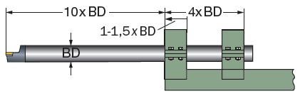
- Surface finish of ~1 μm is required to ensure sufficient clamping contact
- Recommended clamping length is 4 × BD. If possible, we recommend using a clamping length of 6 × BD for boring bars over 200 mm (7.87 inch)
- Cylindrical boring bars in split sleeves. Recommended clamping tolerance is ISO H7
- Split bushing material, minimum 45 HRC to avoid permanent deformation
- If a large bar, use a double bearing cap
- For best clamping stability use a split boring bar holder
Let the design and dimensions of the component decide the diameter and length of the boring bar. For best clamping stability, first choice is Coromant Capto coupling or split sleeves. The diameter of the bore and the length needed to reach the bottom will indicate what type of boring bar to use.
Clamping of Silent Tools bars
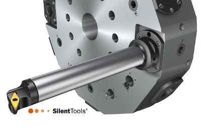
Due to the design of the turret in a CNC lathe or the flexibility of a multi-task machine, the rigidity is usually reduced. Small turret widths reduce the ratio between the clamping length and the bar diameter on larger cylindrical boring bars and consequently reduce the set-up stability.
The Coromant Capto coupling can also be a solution on a turret lathe machine. This minimizes the need for long sleeves and will result in a stable set-up with additional quick-change benefits.
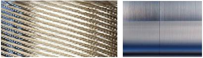
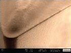
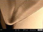
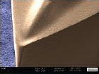
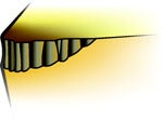
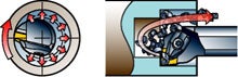
The importance of correct clamping can not be underestimated. The pictures
show surface finish with 1) incorrect clamping and 2) split holder clamping.
Flat bed lathes
Compared to turret lathes, a flat-bed lathe with a tool post is often more rigid and stable and can hold larger and longer boring bars. The limitation of the machine in this case can be the tool post, the size of the machine and the rigidity in the design.
The stability of the machine slides and gibs are important factors in order to achieve good results when holding Silent Tools boring bars with long overhangs. For best results, the tool post clamping should be with large gibs designed with the cross gibs spread widely apart, equal or wider than the clamping length, 4 x BD. Remember that the weight increases dramatically with increased bar size:
- Diameter 100 mm (3.94 inch) = 88 kg (194.0 lb)
- Diameter 120 mm (4.72 inch) = 140 kg (308.7 lb)
| The best tool post design is an A-frame where the bar is mounted directly over and in between the slides of the machine. | 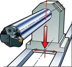 |
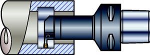
For best performance of the boring bar, the contact, design, and dimensional tolerance between tool and tool holder are important factors. The best stability is obtained with a holder that completely encases the bar. V-type bar holder and cylindrical holder with screws are not recommended.
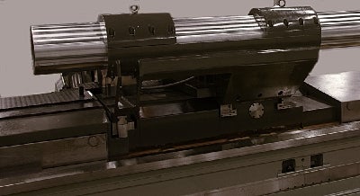
Split holder for 300 mm (11.81 inch) bar diameter. The distance between the cross slides is 1,200 mm (47.24 inch) (4 x BD).
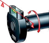
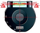
Centre height setting toolFor all cylindrical CoroTurn SL bars, there is a quick and simple method to accurately ensure correct centre height setting of the cutting edge:
Even though the bar will deflect slightly below centre during the machining operation, the correct mounting of the bar is on centre line. Alternative setting tools are height gauge and cross test lever. | 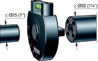 | |
 | ||
 |
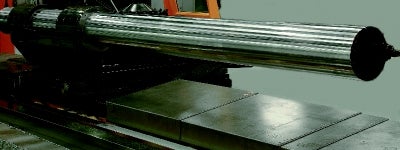
Dampened 300 mm CoroTurn SL quick change boring bar with overhang 10 x BD.
Pressure and direction
For best tool life and process security, use coolant directed to the cutting zone. For tools equipped with SL quick change heads, adjustment of the coolant nozzles needs to be done manually, to ensure that the coolant hits the cutting zone. For best results, use tools with integrated coolant and several nozzles. This is equally important for internal turning with long overhangs. To turn on and off the coolant flow, use a hexagon key.
Clearance between the boring bar and the inside of the bore is extremely important for chip evacuation and to avoid radial deflection. For a bore diameter of 100 mm (3.94 inch), the applicable bar is 80 mm (3.15 inch). This gives enough clearance for chip evacuation and will eliminate any damage to the tool and component.
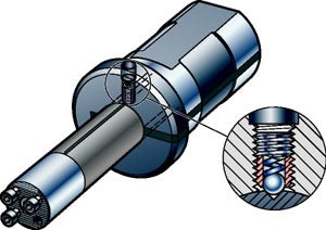
Coolant can be applied through the rear of the boring bar using common size connectors with British Standard Pipe (BSP) threaded fittings. Sandvik Coromant dampened boring bars are equipped with a pre-threaded coolant intake hole.
Factors that influence vibration
To minimize vibration tendencies:
- Use a large entering angle and positive rake angle
- Use small nose radii and point angle
- Use a positive macro geometry
- Control the wear pattern and ER-treatment on the micro geometry
- Depth of cut should be larger than the nose radius.
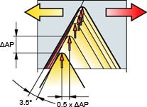
Lower radial force gives less radial deflection and fewer problems with vibration. For best results; use a radial depth of cut that is larger than the nose radius when using a 90° entering angle (0° lead angle). If the radial depth of cut is smaller, a 45° entering angle will give you equal results.
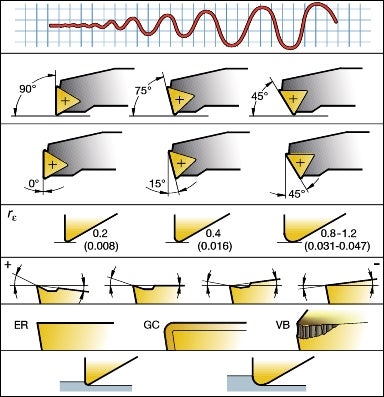 | Vibration tendency |
| Entering angle | |
| Lead angle | |
| Nose radius and point angle. mm (inch) | |
| Macro geometry | |
| Micro geometry | |
| Depth of cut related to nose radius |
Be aware that re-directing forces can reduce deflection:
- Entering angle as close to 90° as possible (lead angle 0°) will maximize the portion of feed force coming back from the workpiece in the axial direction. A force in the axial direction will give less tool deflection than equal forces in the radial direction.
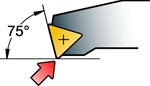
- For internal turning the entering angle should never be less than 75° (lead angle 15°).
- The more positive the rake angle, the less cutting forces are needed to machine the component. Less cutting forces means less deflection.
- Less force in the radial direction giving less radial deflection
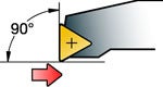 |  | |
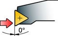 | 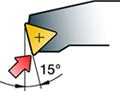 | |
| Force direction: mainly axial | Force direction: both axial and radial | |
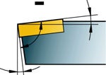 | 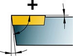 | |
| Negative rake angle increases cutting forces | Positive rake angle gives less cutting forces |
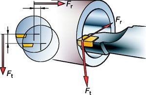
F
t
= tangential forces and Fr = radial forces
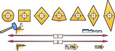
Insert point angle
Select an insert shape relative to the entering angle and accessibility requirements of the tool. One rule of thumb is to always choose the smallest possible nose radius to reduce vibration tendencies. When it comes to point angle, there are two paths to choose:
- A small insert point angle will improve tool stability, give good clearance of a trailing surface, and small chip area variations if the tool starts vibrating in a radial direction
- A large insert point angle gives insert strength and reliability but requires more machining power, since a larger cutting edge is engaged in the cut
Positive geometries
Positive geometries and positive rake angles generate less cutting forces and less deflection of the tool. Therefore, choose the most positive geometry you can, with a chip-breaker suitable for your cutting data. This may decrease the wear resistance and edge strength somewhat, as well as the chip-control, so vibration control is always a balance.
Wiper inserts
Wipers are usually not first choice when it comes to avoiding vibration, as the increased cutting forces and radial deflection are difficult to overcome. In very stable conditions, however, wiper inserts can provide true benefits in surface finish and increased cutting data.
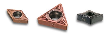
Edge roundingA small edge rounding (ER) gives lower cutting forces in all directions. This means easier cutting action and less deflection of the tool. Ground inserts have smaller edge rounding than direct pressed inserts, which is true also for uncoated or thin-coated inserts. | 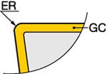 |
 |  |  | ||
| M = Direct pressed inserts | G = Ground insert, normally with smaller ER | E = Ground insert for closer tolerances and sharp edge |
Cutting data
Excessive insert wear, such as flank wear must be avoided, as it changes the clearance between the tool and the component wall, which can cause vibration problems.
 |  |
 |
Cutting speed, vc
Correct cutting speed will avoid built-up edge, which influences surface finish, cutting forces and tool life.
- Excessive cutting speed can generate flank wear, which reduces security and reliability, due to chip jamming, poor chip evacuation and insert breakage, especially when machining deep holes
- Cutting speeds which are too low will generate built-up edge
- Uneven wear pattern will decrease tool life and surface finish, so pay careful attention to wear pattern
- Workpiece material has a great impact on what cutting speed you can apply
Depth of cut, ap, and feed, fn
The combination of ap and fn is important to achieve the best possible chip areas. Two rules of thumb:
- Program ap larger than the nose radius
- Program for an fn that is a minimum of 25% of the nose radius, depending on what surface finish is required
One of the first things to consider if you experience vibration when machining with long overhangs is to increase the feed and as second remedy change the cutting speed. Usually, the best results are achieved with higher cutting speed.
Chip area
- If the chip area is too large, the cutting forces are too large
- If the chip area is too small, the friction between tool and workpiece is too great and a rubbing effect can occur
Tips and tricks
Reduce the risk of vibration by choosing the largest possible bar diameter with the smallest possible overhang. Use recommended clamping length, minimum 4 x BD.
Cut off of the CR boring bars above 10 x BD is not allowed. For 570-4C bars, clamping over the dampening mechanism is allowed, while it is not allowed for 3C bars. When a 570-3C short design bar is cut-off to minimum length, the clamping length must not exceed 3 x BD to avoid clamping over the dampening mechanism. Never cut-off 570-3C bars diameter >100mm (3.94 inch).
Modification of standard bars
| Bar diameter | L, min length after cut off | |
| BD | Short design 4–7 × BD | Long design 7–10 × BD |
| mm | mm | mm |
| 16 | 100 | 155 |
| 20 | 125 | 200 |
| 25 | 155 | 255 |
| 32 | 190 | 320 |
| 40 | 240 | 410 |
| 50 | 305 | 520 |
| 60 | 380 | 630 |
| 80 | 630 | 630 |
| 100 | 770 | 770 |
We recommend a min. clamping length of 4 × BD
| Bar diameter | L, min length after cut off | |
| BD | Short design 4–7 × BD | Long design 7–10 × BD |
| inch | inch | inch |
| 0.625 | 4 | 7 |
| 0.750 | 5 | 8 |
| 1.000 | 7 | 11 |
| 1.250 | 8 | 13 |
| 1.500 | 10 | 17 |
| 1.750 | 10.4 | 18 |
| 2.000 | 12 | 21 |
| 2.500 | 15 | 25 |
| 3.000 | 20 | 20 |
| 4.000 | 30.3 | 30.3 |
We recommend a min. clamping length of 4 × BD
Two lines on the bar indicate minimum and maximum overhang. Make sure that the overhang is within that range. Outside this range, there is no guarantee for the dampening function.
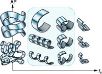
Chip evacuation
For best chip evacuation, use a tool holder with integrated coolant and an insert geometry that gives short and spiral formed chips. If you experience poor chip evacuation; try to increase the coolant flow, change the insert geometry or increase the cutting speed to get shorter chips.
Another alternative is to consider an alternative tool path. Up-sidedown
cutting units actually permit improved chip evacuation.
Ensure that there is enough room for the chips between bar and hole. Otherwise, the tool can press the chips onto the surface and also damage the tool body.
 |  |
Adjustment of nozzles
Use a hexagon key to turn the coolant flow on or off. For SL Quick Change heads, use the same hexagon key to adjust the direction of the nozzles.
Wiper inserts
For better surface finish and higher productivity, wipers can be an optimizer in very stable conditions. General recommendations when using wipers are to increase the feed and choose a smaller nose radius.
Internal threading
To reduce the risk of vibration, use the following tips:
- Use modified flank feed
- Infeed per pass should not exceed 0.2 mm (0.0078 inch) and never be less than 0.06 mm (0.0024 inch)
- Final pass, always with reduced infeed rate
- Use a sharp geometry for lowest cutting forces
For best chip evacuation:
- Use modified flank feed to lead the spiral chips towards the opening of the hole
- Use inside-out feed direction in stable conditions. Choose left or right flank to steer the chip flow
- Use coolant for best chip evacuation
| Chip direction | Feed direction | ||
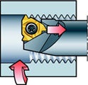 |  | ||
| Feed direction from inside out | Modified flank infeed directs the chips out from the hole |
Internal grooving and profiling
Reduce the risk of vibration by applying the following tips:
- Set-up should have the shortest possible overhang with the lightest cutting geometry possible
- Use a smaller insert and make several cuts instead of one
- Start from the outside and make overlapping cuts inwards for best chip evacuation
- A finishing operation can be a side turning motion. Start from the
inside and turn outwards - Ramping/turning can be used for improved chip control and may reduce vibration
- Use right- or left hand style inserts to direct the chips when roughing
Common set-up
Running the bar conventionally generates cutting forces that push the insert downwards.
Alternative set-up
Running the bar upside down changes the direction of the cutting forces which improves the stability. This can also improve chip evacuation. This method requires careful considerations, even in small diameters. If the cutting force is reduced to 0 by interrupted cut, the bar will bounce against the workpice in turning direction and receives a lager cut force which can damage both tool and component.
Treatment
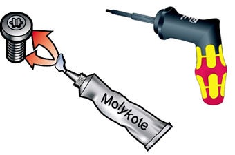
For best performance, clean all parts and lubricate with oil at least once a year. Lubricant should also be applied to the screws when needed. Replace worn or exhausted screws and washers.
Dampened bars can become deformed due to the thin wall thickness. When assembling, ensure that the bars are held correctly. Always check the clamping when working with Silent Tools products. Use a torque wrench for correct screw-tightening.
Summary: How to avoid vibration
Increase static stiffness
- Check the clamping and set-up
- Use Coromant Capto or split holder
- Minimum tool overhang and maximized diameter
- Material reinforcement (boring bars)
Increase dynamic stiffness
- Small insert point angle
- Use dampened tools
- As low weight in front of the cutting tool as possible
Reduce the cutting forces
- Use a positive cutting angle
- Use a positive insert geometry with small ER
Avoid deflection
- Change the direction of the cutting force from radial to axial
- Entering angle close to 90° (lead angle 0°)
- Depth of cut bigger than nose radius
Enable chip control
- Increase coolant flow
- Clearance between tool and workpiece
- Check that all chips have been evacuated
Note!
Be sure not to overload the dampened boring bar. Maximum load is marked on the products and you can also use the calculator available at www.sandvik.coromant.com/calculators to find maximum load.
