
CoroDrill® DE10
The exchangeable-tip drill for high-volume hole making
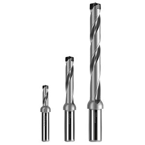
Apply 3–8×DC drills
There is no difference in applying 3×D or 8×D regarding feed recommendations. The applied cutting data should be within the recommendations.

CoroPlus® Tool Guide
Find the latest updated cutting data for all material groups and articles in CoroPlus® Tool Guide. Set the workpiece parameters and the system generates starting point cutting data.
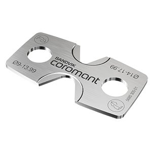
Mounting key
A mounting key is included in each drill box and covers the complete drill range. The mounting key gives great visibility during the assembly process and is easily recyclable.
Order no: 5680 300-01
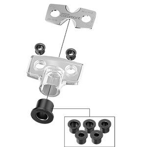
Plastic cover with collars
The plastic cover improves ergonomics and avoids splinter risks of carbide. The see-through design and guiding collars make it easy to use.
Order no: 5680 300-20
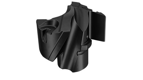
Assembly instruction
- Lubricate the contact surfaces before mounting the drill tip to maximize the interface tool life.
- Place the drill tip into the tip seat ~60 degrees twisted from the final position. Position the key in the key grips.
- Mount/unmount the tip.
Grade and geometry recommendations
-M5 geometry
- One geometry for all materials
Grade GC4334
- Tough, high Cr content and fine-grained substrate with PVD coating (AlTiN) produced with Zertivo® technology
- High reliability with high edge security provides resistance against built-up edge and chipping
Grade GC2334

- Tough, high Cr content and fine-grained substrate with thin multi-layer PVD coating (AlTiCrN) produced with Zertivo® technology
- For high reliability and improved resistance against chipping and flaking on land margin
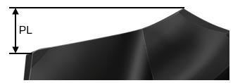
Through hole recommendations
When drilling through holes with -M5 geometry, use point length (PL) + 1 mm (0.039 inch) to ensure the drill tip is completely through the hole exit. The exact PL value is found on the article’s web page.
| Drill tip interface size | DC min–max, mm | PL min–max | PL min–max |
| mm | inch | ||
| 090 | 09.00–09.49 | 1.27–1.31 | 0.050–0.052 |
| 095 | 09.50–09.99 | 1.34–1.38 | 0.053–0.054 |
| 100 | 10.00–10.49 | 1.41–1.45 | 0.056–0.057 |
| 105 | 10.50–10.99 | 1.48–1.52 | 0.058–0.060 |
| 110 | 11.00–11.49 | 1.55–1.59 | 0.061–0.063 |
| 115 | 11.50–11.99 | 1.62–1.66 | 0.064–0.065 |
| 120 | 12.00–12.49 | 1.69–1.73 | 0.067–0.068 |
| 125 | 12.50–12.99 | 1.76–1.80 | 0.069–0.071 |
| 130 | 13.00–13.49 | 1.83–1.87 | 0.072–0.074 |
| 135 | 13.50–13.99 | 1.90–1.94 | 0.075–0.076 |
| 140 | 14.00–14.99 | 1.99–2.07 | 0.078–0.081 |
| 150 | 15.00–15.99 | 2.13–2.21 | 0.084–0.087 |
| 160 | 16.00–16.99 | 2.27–2.34 | 0.089–0.092 |
| 170 | 17.00–17.99 | 2.41–2.49 | 0.095–0.098 |
Advanced operations
Note: These advanced operations are not recommended, but if necessary, follow the guidelines below. Results may vary depending on workpiece material and drill length.
| Angled surface entry | Angled suface exit | Convex surface | Concave surface | Cross holes | |
| Preconditions | Angle ≤ 10º | Angle ≤ 30º | Minimum radius of surface: 4×DC | Minimum radius of surface: 1×DC | Minimum recommended diameter on the hole to be crossed: 2×DC |
| Cutting speed, vc | Use the recommended value for the workpiece material | ||||
| Feed, fn | Start value; reduce to 1/3 of recommended feed rate | ||||
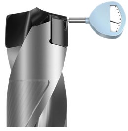
Run-out recommendations
Run-out is affected by for example machine condition, holder and mounting.
Preferable: ≤ 0.03 mm (0.0012 inch)
Acceptable: ≤ 0.06 mm (0.0024 inch)
Not acceptable: > 0.06 mm (0.0024 inch)
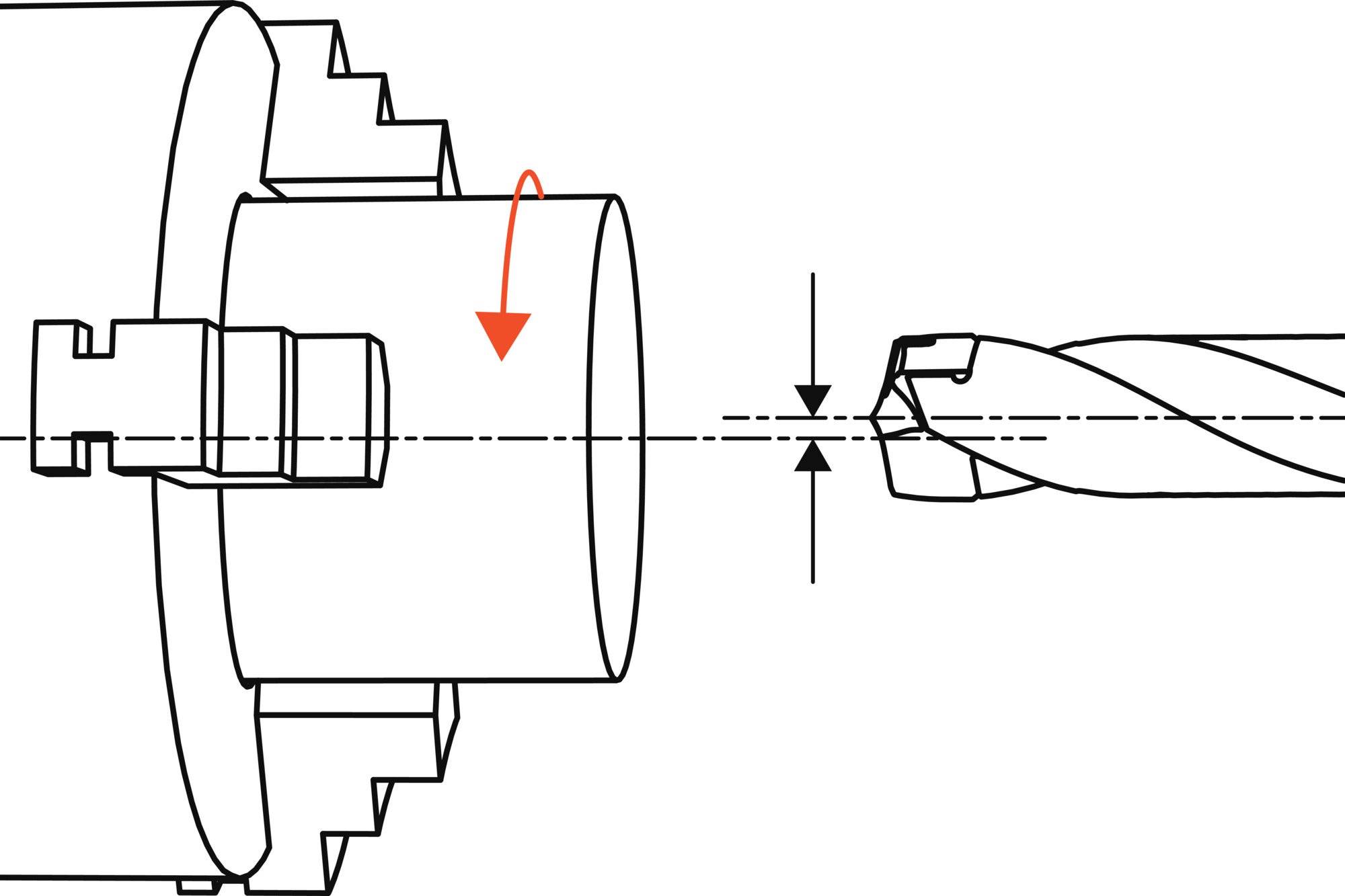
Turning applications
In non-rotating drill applications, a large misalignment greatly affects process security and tool stability. Always follow these recommendations.
Preferable ≤ 0.10 mm (0.0039 inch)
Acceptable ≤ 0.20 mm (0.0079 inch)
Not acceptable > 0.20 mm (0.0079 inch)
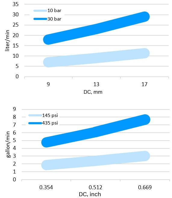
Coolant recommendations
- Internal coolant is recommended for safe chip evacuation
- Apply sufficient coolant flow and follow the recommendation on emulsion concentration from your supplier
- When drilling deep holes, sufficient coolant flow is crucial to enable proper chip evacuation
Recommended minimum cutting fluid flow
Join us. Stay updated.
Sign up for our newsletter today

Sandvik Coromant UK
+44 (0)121 368 0305