
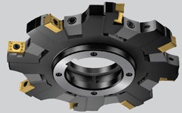
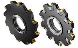
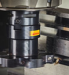
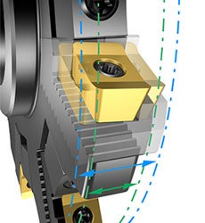
CoroMill® 331
Fraise-disque polyvalente
r.Settings
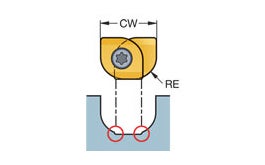
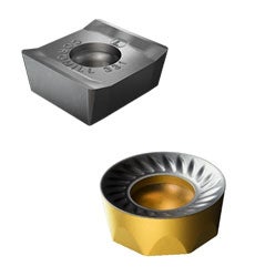
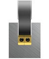
Working with large corner radius inserts
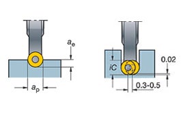
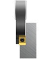
Working with round inserts
For grooves deeper than IC/2, a 0.5 mm (0.020 inch) adjustment of each cassette is recommended
Application tips
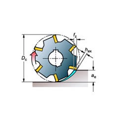
Épaisseur maximum des copeaux
Dans les applications de tronçonnage et d'usinage de gorges, le paramètre le plus important est l'épaisseur maximum des copeaux (hex).
• Le rapport de l'engagement de la fraise par rapport à son diamètre est toujours inférieur à 30%
• Utiliser une valeur de hex optmiale en fonction du rapport ae/DC afin d'éviter les frottements au lieu de la coupe en cas d'épaisseur des copeaux trop faible
• Une valeur de hex correcte permet d'obtenir une bonne action de coupe produisant un état de surface meilleur et une durée de vie de l'outil plus longue
Choix d'une nuance
• Les nuances PVD sont le premier choix pour les applications d'usinage de gorges
• Pour les applications avec des fraises-disques deux tailles, les nuances CVD sont à privilégier
Liste de contrôle pour les fraises-disques
Retirez le maximum de vos opérations de rainurage grâce à ces indications utiles.
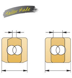
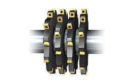
Réduction des problèmes de chevauchement
• Utiliser des plaquettes Tailor Made avec une longueur d'arête de coupe réduite
• Réduction de l'usure dans la zone de chevauchement
• Meilleur contrôle des copeaux et jusqu'à 10% de puissance consommée en moins
Recommendations
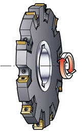
Cutter body selection
- The cutters are designed and named after their application area, for example full side & face, half side & face, back face.
- For a required ar, use smallest cutter diameter for best stability
- For a fixed diameter, use cutter with high zn for higher productivity
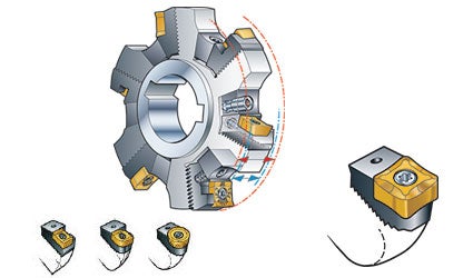
Full side & face cutter
| Right-hand cutter | |
| Right-hand cassette |
|
| Left-hand cassette | |
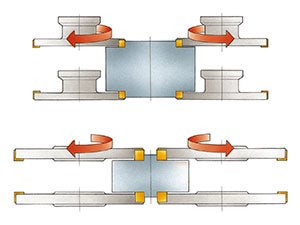
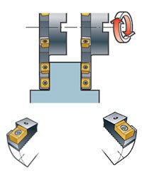
Half side & face cutter
| Spindle rotation R | Spindle rotation L | ||
| R style cutter R331.52…R R Cassette |
|
L style cutter L331.52…L L Cassette |
|
| R style cutter R331.52…L L Cassette |
L style cutter L331.52…R R Cassette |
||
| R style cutter R331.52 |
L style cutter L331.52 |
||
| L style cutter L331.52 |
R style cutter R331.52 |
||
Cutting edge length
Smallest cutter width is always recommended when selecting full side and face milling cutter for grooving. Optimizing the overlap of two inserts is critical for stable machining.
Choice of cassette
Half side and face mill
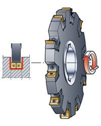
Full side and face mill
Note: The cutter diameter, DC, will be 3.2 mm (0.126 inch) larger with the 8 edge square insert.
First choice insert
Full side & face milling
| Roughing | M30 4330 | L50 2040 | M30 3040 | WL H13A | L50 S30T | M30 1130 |
| Medium | M30 1130 | L50 1040 | M30 1020 | NL H13A | L50 S30T | M30 1130 |
| Finishing | L50 1130 | L30 1040 | KL 1020 | NL H13A | L30 S30T | PL S30T |
| P | M | K | N | S | H |
The recommendations are based on dry conditions for all material groups except for ISO-S where wet conditions are recommended. If wet conditions, consider a PVD coated grade.
Half side & double half side milling
| Roughing | PM 4330 | L50 2040 | KM 3330 | WL H13A | L50 S30T | M30 4330 |
| Medium | M30 4330 | L50 2040 | M30 3040 | NL H13A | L50 S30T | M30 1130 |
| Finishing | L50 1130 | L30 1040 | M30 1020 | NL H13A | L30 S30T | PL S30T |
| P | M | K | N | S | H |
The recommendations are based on dry conditions for all material groups except for ISO-S where wet conditions are recommended. If wet conditions, consider a PVD coated grade.
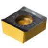
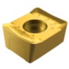
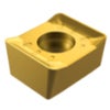
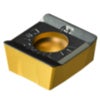
Choice of geometries
| Easy, good conditions | Tough, bad conditions | ||||
|
|
|||||
| Sharpness | Toughness | ||||
|
|
|
|
|
|
| H-NL | L30 | X-XL | L50 | M30 | X-XM |
Cutting data
| Ordering code | ISO material | fz | hex | ||
| Starting value | Min.-max. | Starting value | Min.-max. | ||
| N331.1A-……E-L30 |
|
0.06 | (0.01‒0.08) | 0.05 | (0.01‒0.07) |
| N331.1A-……E-L50 |
|
0.09 | (0.02‒0.17) | 0.08 | (0.02‒0.15) |
| N331.1A-……E-M30 |
|
0.14 | (0.05‒0.20) | 0.12 | (0.04‒0.17) |
| N331.1A-…...x-NL |
|
0.12 | (0.01‒0.17) | 0.10 | (0.01‒0.15) |
| N331.1A-…...x-xL |
|
0.12 | (0.04‒0.17) | 0.10 | (0.03‒0.15) |
| N331.1A-...…x-xM |
|
0.12 | (0.04‒0.17) | 0.10 | (0.03‒0.15) |
| N331.1A-...…x-xM |
|
0.17 | (0.06‒0.29) | 0.13 | (0.05‒0.25) |
| R/L331.1A-……H-WL |
|
0.09 | (0.02‒0.12) | 0.08 | (0.02‒0.10) |
| R/L331.1A-……H-WL |
|
0.12 | (0.05‒0.17) | 0.10 | (0.04‒0.15) |
Abonnez-vous pour rester informé(e).
Abonnez-vous dès aujourd'hui à notre e-newsletter

Sandvik Coromant France - Customer Service
+33246840057