
CoroMill® MS20
Shoulder milling redefined
Assortment overview
Cutter bodies
| Cutter diameter range | 15.8–84 mm (inch equivalent) | |
| Cutter body interface | Cylindrical shank, Coromant® EH, MSSC, Arbor, Coromant Capto® and Weldon (inch) | 119 articles |
| Cutter body interface | CIS and Weldon (metric) | 13 articles |

CAPP family M253 is available for cutter bodies.
Inserts
| Insert IC size | IC10 |
| Insert geometry | E-L50, M-M20 and M-M30 |
| Insert corner radius | 0.2, 0.4, 0.8 and 1.6 |
| Insert grade | 1040, 2040, S30T and S40T |
| Number of articles | 27 |
Cutting data
hex recommendations
| ISO area | Grades | hex, mm (inch) | hex, mm (inch) | hex, mm (inch) |
| | | E-L50 | M-M20 | M-M30 |
| M1.0.Z.AQ (1.4404 / 316L) | 1040, 2040 | 0.1 (0.05–0.15) .004 (.002–.006) | 0.1 (0.08–0.15) .004 (.003–.006) | |
| M3.2.Z.AQ (SAF2205) | 1040, 2040 | 0.08 (0.05–0.12) .003 (.002–.0047) | 0.08 (0.05–0.12) .003 (.002–.0047) | |
| S4.2.Z.AN (TiAl6V4) | S30T | 0.1 (0.05–0.15) .004 (.002–.006) | 0.1 (0.08–0.15) .004 (.003–.006) | 0.13 (0.08–0.2) .0051 (.003–.008) |
| S2.0.Z.AG (Inconel 718) | S30T, 2040 | 0.08 (0.05–0.12) .003 (.002–.0047) | 0.08 (0.05–0.12) .003 (.002–.0047) | 0.1 (0.08–0.15) .004 (.003–.006) |
Cutting speed recommendations
| Material | Grade | vc m/min (ft/min) |
| M1.0.Z.AQ (1.4404 / 316L) | 1040 | 75–155 (246–509) |
| 2040 | 90–135 (295–443) | |
| S30T | 90–155 (295–509) | |
| S40T | 135–235 (443–771) | |
| M3.2.Z.AQ (SAF2205) | 1040 | 80–110 (262–361) |
| 2040 | 90–135 (295–443) | |
| S30T | 90–130 (295–427) | |
| S40T | 90–135 (295–443) | |
| S4.2.Z.AN (TiAl6V4) | 2040 | 35–80 (115–262) |
| S30T | 35–105 (115–344) | |
| S40T | 35–60 (115–213) | |
| S2.0.Z.AG (Inconel 718) | 2040 | 30–50 (98–164) |
| S30T | 30–55 (98–180) | |
| S40T | 25–50 (82–164) |
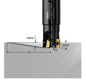
Cutting data, APMX and AZ
| APMX | 9.0 mm (0.35 inch) |
| Recommended ap | 4.0 mm (0.16 inch) |
| AZ | 1.0 mm (0.04 inch) |
Cutting data, linear and helical ramping
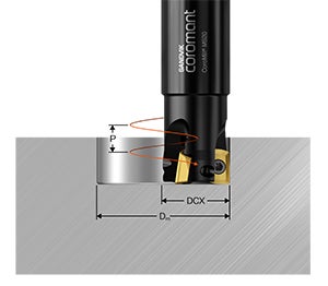
| DCX, metric | DCX, inch | RMPX (deg) | Lm, mm (inch) | Max Dm, mm (inch) | Flat min Dm, mm (inch) | Min Dm, mm (inch) |
| | ⅝" | 7.8 | 65.7 (2.85) | 30.15 (1.19) | 27.75 (1.08) | 23.75 (0.93) |
| 16 mm | | 7.7 | 66.6 (2.61) | 30.4 (1.2) | 28 (1.10) | 25 (0.97) |
| | ¾" | 5.4 | 95.2 (2.57) | 36.5 (1.44) | 34.1 (1.33) | 30.1 (1.18) |
| 20 mm | | 4.9 | 105 (4.13) | 38.4 (1.50) | 36 (1.42) | 33 (1.3) |
| 25 mm | | 3.3 | 156.1 (6.15) | 48.4 (1.91) | 46 (1.80) | 43 (1.68) |
| | 1" | 3.2 | 161 (6.34) | 46.8 (1.82) | 46.8 (1.83) | 42.8 (1.68) |
| | 1 ¼" | 2.2 | 234.3 (9.21) | 61.9 (2.44) | 59.5 (2.33) | 55.5 (2.18) |
| 32 mm | | 2.2 | 234.3 (9.21) | 62.4 (2.46) | 60 (2.35) | 57 (2.23) |
| | 1 ½" | 1.7 | 303.2 (11.94) | 72.2 (2.83) | 72.2 (2.83) | 68.2 (2.68) |
| 40 mm | | 1.6 | 322.2 (12.68) | 78.4 (3.09) | 76 (2.98) | 73 (2.86) |
| 50 mm | | 1.2 | 429.7 (16.92) | 98.4 (3.86) | 96 (3.78) | 93 (3.65) |
| | 2" | 1.2 | 429.7 (16.92) | 97.6 (3.83) | 97.6 (3.83) | 93.6 (3.68) |
Cutting data, plunge milling
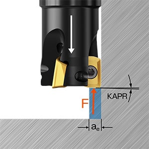
Axial cutting forces
| ISO area | Reference material | Max ae, mm (inch) | Feed, mm/z (in/z) |
| ISO M | M1.0.Z.AQ (1.4404 / 316L) | 4 (0.157) | 0.10 (0.08–0.15) (0.004 (0.003–0.006)) |
| ISO M | M3.2.Z.AQ (SAF2205) | 4 (0.157) | 0.08 (0.05–0.12) (0.003 (0.002–0.0004)) |
| ISO S | S4.2.Z.AN (TiAl6V4) | 3 (0.118) | 0.08 (0.05–0.12) (0.003 (0.002–0.0004)) |
| ISO S | S2.0.Z.AG (Inconel 718) | 3 (0.118) | 0.08 (0.05–0.12) (0.003 (0.002–0.0004)) |
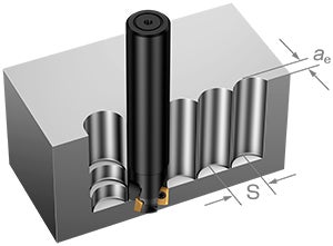
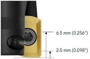
Variable depth of cut
- For increased insert tool wear especially in ISO M materials, depth of cut (ap) can be modified at each pass so that the notch wear will develop slower
- Value of the offset for ap: 25–75% of APMX
2.5 to 6.5 mm (0.098 to 0.256 inch) recommended for CoroMill® MS20
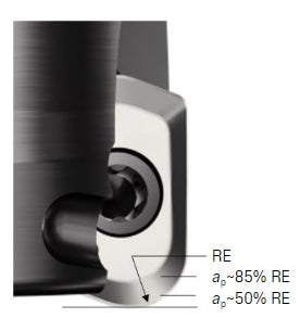
Use of large radius
- A bigger corner radius of the insert increases security, especially in cornering for pocket milling operations, as well as ramping with bigger ramping angle value
- Cutting force / spindle load will increase
- Surface finish will be inferior
- May lead to vibrations in overhang applications
- When used at ap ≤85% RE, the notch wear characteristic is minimized
- When used at ap ≤ 50% RE, high-feed milling strategies can be applied
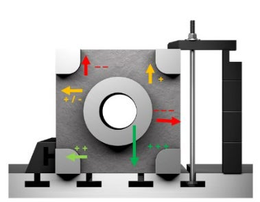
Fixture limitations
- Fixturing must be considered when choosing direction of cut and while changing direction
- Direction of cut towards the machine table gives highest stability followed by rigid support directly mounted on the table
Machining challenges in ISO M
Applications
- Open and closed pocket milling
- Full slotting and hole making with helical ramping cycles
- Long overhang cavity milling
- Low engagement shoulder milling
- Multi-task turn milling
Challenges
- Chip formation
- Insert security and reliability
- Long overhang machining
- Predictable and repeated tool life
CoroMill® MS20 solution
- Use M-M20 geometry for excellent chip formation and evacuation in sticky materials
- M-M30 geometry gives higher security in tougher materials (duplex). Higher edge line toughness of the geometry allows the insert to be used with higher productivity (high cutting data) in stable operations
- Use E-L50 geometry for long overhang applications where a sharper and hence lighter cutting edge will help reduce vibrations
- Robust steel shank design ensures better stability and less deflection
- The two cutting edges have equal tool life and the M-M20 geometry provides predictable and gradual wear characteristics, especially in austenitic stainless steel
Machining challenges in ISO S
Applications
- Open and closed pocket milling
- Full slotting and hole making with helical ramping cycles
- Long overhang cavity milling
- Low engagement shoulder milling
- Multi-task turn milling
Challenges
- Chip evacuation
- Insert security and reliability
- Tool life
- Cutter body damage (chip rubbing)
CoroMill® MS20 solution
- Use E-L50 geometry for excellent chip formation and evacuation in sticky materials
- M-M20 and M-M30 geometries give higher security in tougher applications in titanium and Inconel, respectively
- The higher edge line toughness of these geometries allows the inserts to be used with higher productivity (high cutting data) in stable operations
- Robust steel shank design ensures better stability and less deflection. The improved tool body material can withstand chip rubbing better
CoroPlus® Tool Guide for CoroMill® MS20

- For quick and accurate tool recommendations tailored to your specific application requirements, use online tool selector CoroPlus® Tool Guide
- Choose the correct tool and parameters for your application, based on tool, operation, material and machine
- Easy to use, easy to choose
- Supports all CoroMill® MS20 application areas
Join us. Stay updated.
Sign up for our newsletter today

Sandvik Coromant UK
+44 (0)121 368 0305