
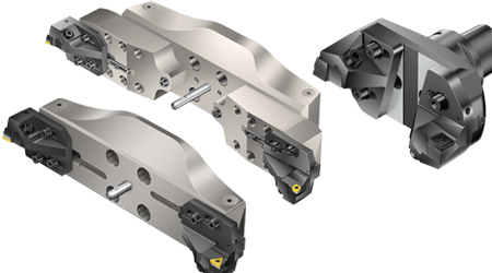
Diameter 148–1260 mm (5.91–49.61 inch)
 |  |  | |||
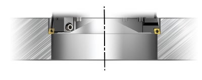 |  | 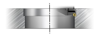 | |||
| Productive boring | Step-boring | Single-edge boring | |||
| Requirements: | |||||
| 1 adaptor 2 extension slides 2 cartridges | 1 adaptor 2 extension slides 2 cartridges | 1 adaptor 1 (2) extension slides 1 (2) cartridges Second slide and cartridge used as counterweight |
Tool mounting
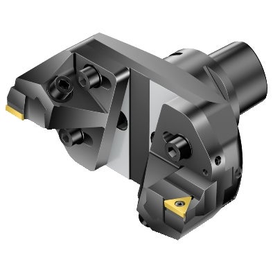
Diameter 148–300 mm (5.83–11.81 inch)
- Fit slides to adaptor and place washers on clamping screws.
- Place cartridges to slides and place cup-springs on clamping screws.
- Tighten clamping screws on slides finger-tight, tight so that the slides and cartridges can be easily moved.
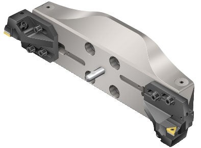
Diameter 298–540 mm (11.81–21.26 inch)
- Fit slides to bridge in the right position depending on diameter range.
- Place cartridges to slides.
- Place cup-springs on clamping screws.
- Tighten clamping screws on slides, finger-tight tight so that the slides and cartridges can be easily moved.
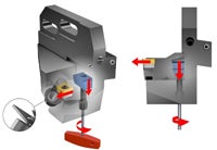
The cup spring pressure prevents the slide from moving when locking the slide screws, or by gravity when adjusting while tool mounted in the machine.
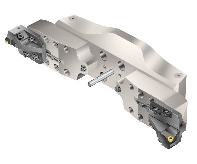
Diameter 538–1260 mm (21.18–49.61 inch)
- Fit bridge extensions to bridge in the right position depending on diameter range.
- Tighten with screws, check the correct torque.
- Fit slides on the bridge extensions in the right position depending on diameter range.
- Place cartridges to slides.
- Place cup-springs on clamping screws.
- Tighten clamping screws on slide finger-tight so that the slides and cartridges can be easily moved.
The cup spring pressure prevents the slide from moving when locking the slide screws, or by gravity when adjusting while tool mounted in the machine. Make sure the cup-spring is positioned according to the illustration.
Tool setting
Productive boring
- Pre-stress clamping screws of the cartridge for smooth setting.
- Adjust with the setting screw until insert nose radius reaches set length.
- Always adjust the length from a smaller to a larger value
- Lock the cartridge clamping screw.
- Adjust the cartridges (axially):
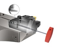
- Adjust the slides (radially):
- Pre-stress clamping screws of the slides for smooth setting.
- Adjust with the setting screw until insert nose radius reaches set diameter.
- Always adjust the diameter from a smaller to a larger value
- Lock the slide clamping screws.
- Mount inserts.
- Place tool in pre-setter.
- Rotate tool until largest diameter on selected slide is found. Lock this position at the pre-setter.
- To set desired diameter on tool pre-setter:
- Repeat for slide 2.
- Tighten clamping screws on slides and cartridges. See handling instruction below to get the recommended tightening torque for your boring tool (can be done outside the tool pre-setter if needed).
- Check diameter and length of tool in the tool pre-setter. If possible, transfer tool data to machine control system.
Step-boring
Set the two slides to different diameters and heights. The slide at the smaller diameter needs to be set to the longer axial position; the slide at the final diameter represents a shorter tool length. The axial difference of both cutting edges needs to be at least half the feed rate. The feed rate per tooth is equal to the feed rate per revolution.
- Pre-stress clamping screws of the cartridge for smooth setting.
- Adjust with the setting screw until insert nose radius reaches set length.
- Always adjust the length from a smaller to a larger value
- Lock the cartridge clamping screw.
- Adjust the cartridges (axially):
- Adjust the slides (radially):
- Pre-stress clamping screws of the slides for smooth setting.
- Adjust with the setting screw until insert nose radius reaches set diameter.
- Always adjust the diameter from a smaller to a larger value
- Lock the slide clamping screws.
- Mount inserts.
- Place tool in pre-setter.
- Rotate tool until largest diameter on selected slide is found. Lock this position at the pre-setter.
- Note: Total depth of cut should be divided into two equal parts to keep the tool as balanced as possible.
- To set desired diameters on tool pre-setter :
- Repeat for slide 2.
- Tighten clamping screws on slides and cartridges. See handling instruction below to get the recommended tightening torque for your boring tool (can be done outside the tool pre-setter if needed).
- Check diameter and length of tool in the tool pre-setter. If possible, transfer tool data to machine control system.
Single-edge boring
- Axial adjustment is not needed. Lock the cartridge clamping screw.
- Adjust the slides (radially):
- Pre-stress clamping screws of the slides for smooth setting.
- Adjust with the setting screw until insert nose radius reaches set diameter.
- Always adjust the diameter from a smaller to a larger value.
- Lock the slide clamping screws.
- Mount insert on one cartridge. Note: The other slide with cartridge is used to balance the tool.
- Place tool in pre-setter.
- Rotate tool until largest diameter on selected slide is found. Lock this position at the pre-setter.
- To set desired diameter on tool pre-setter:
- Repeat for slide 2.
- Tighten clamping screws on slides and cartridges. See handling instruction below to get the recommended tightening torque for your boring tool (can be done outside the tool pre-setter if needed).
- Check diameter and length of tool in the tool pre-setter. If possible, transfer tool data to machine control system.
Diameter 298–1260 mm (11.73–49.61 inch)
Multi-edge boring
Recommended method for diameter setting is a pre-setter or using machine table as reference together with a pre-set gauge. The scale markings are helpful features for rough setting of the slides if a pre-setter is not available. The setting screw and cup spring are very useful features for easy and smooth setting of the slides, especially when the tool is mounted in the spindle.
The central pin is a good feature for setting of the slides if a pre-setter is not available: Measure the distance from the central pin to the cutting edge and substract the radius of the central pin (8 mm (0.315 inch)) to get the radial position of the cutting edge.
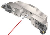
Central pin
