
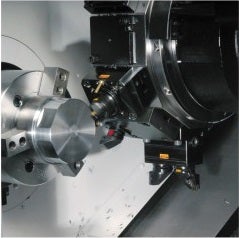
Turning centres
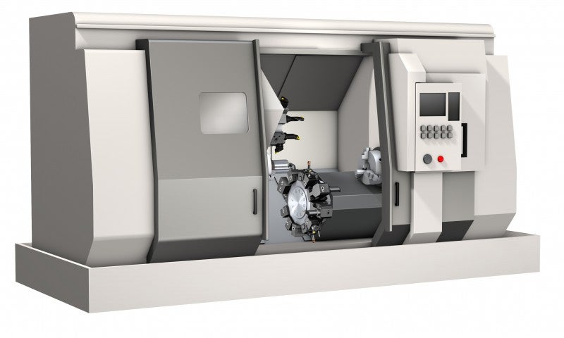
Turning centres have multifunctional capabilities and multi-axis capabilities. This means that you might have a C-axis, Y-axis and driven tools on the turret to be able to perform not only turning but also milling, drilling and tapping operations.
Turning centres machine configuration
There are several machine options to consider depending on the type of component being produced. Careful considerations will ensure an optimal and secure machining process.
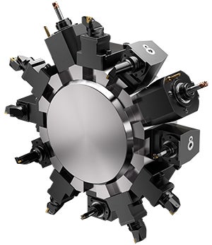
Turret interface
The development of driven tool holders has lead to turning centres becoming truly multifunctional machines.
The two traditional types of turret, shank and VDI, were developed when turning centres only carried out turning and centre line drilling operations. Shank and VDI are suitable for traditional turning centres.
Shank tool interface
VDI
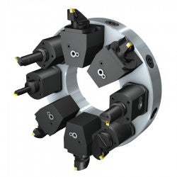
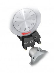
CBI (Coromant Capto® Bolt interface) is well suited for multifunctional turning centres. This interface has more room inside the turret for the driven tool holder bearings, providing best stability and shortest gauge lengths. CBI is unique to each machine tool builder which means that machine adapted clamping units (MACU) that suit the specific machine model are needed.
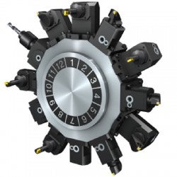
CDI (Coromant Capto® Disc interface) is a standardized turret interface that fit multiple machine brands and models. It is mainly European machine builders who supply CDI as a replacement to VDI.
CBI
CDI
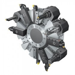
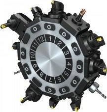
Different configurations of MACU allow the turret to be configured to each production environment mixing the right combination of external, internal, static and driven. Double clamping units are often used to increase the number of tool positions.
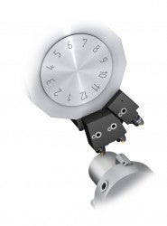
Driven tool
Driven tools allow milling and drilling operations with C-axis control required on the main spindle. 2-axis operations can be carried out, for example keyway slots or holes on the centre line. To be able to mill pockets or drill off-centre line, a Y-axis option is needed.
For drilling operations it is best to use driven tool holders with internal coolant supply and high pressure coolant to provide the best chip evacuation and process security.
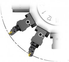
Y-axis/half turret
A Y-axis makes it possible to use driven tools for 3-axis milling and drilling off-centre line. Most features requiring milling operations benefit from Y-axis. Double turning positions can be added, increasing the number of tools for sister tooling or increasing the variety of holders reducing the need to change tool holder styles.
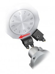
Y-axis
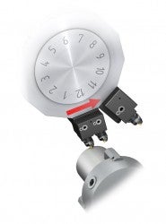
Half turret indexing allows double turning positions to be used increasing the number of tools. This option is not required if a Y-axis is available, therefore it is generally selected on turning centres without driven tools.
Half turret
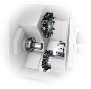
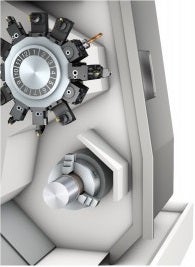
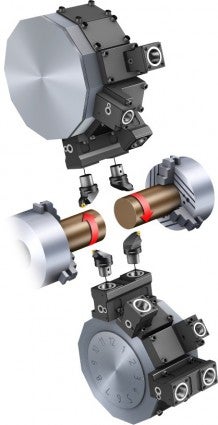
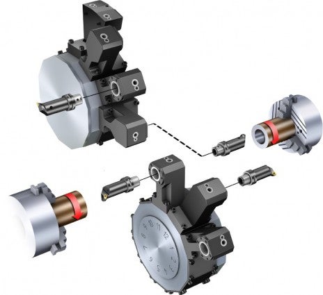
Sub-spindle/lower revolver
To be able to complete a part, often machining from both sides is required. Sub-spindles are often used in combination with a bar feed and with this combination unmanned production of completed parts is possible.
For higher volume production the lower revolver can halve the cycle time compared to a single revolver. A lower revolver enables tandem turning and permits machining operations on the sub-spindle at the same time as the main spindle, offering lower cycle time. Typical applications are long slender components like shafts and components machined on both sides using the sub-spindles.
The drawbacks of the lower revolver are reduced component diameter and increased programming and set-up time making it suitable mainly for turning centres bought for specific components.
Tool holder offset function
When pre-measuring the tools outside the machine it is important to have an optimized zero position for each clamping position. Tool holder offset function allows for a pre-measured tool to be put in any clamping unit and cut correct from the first component being produced, saving measuring time and reducing scrap components.
High pressure pump
Most machines offer a high pressure coolant capability around 70 bar (1015 psi).
Read more about coolant aspects
Automation
Future machine and tooling requirements are driven by common challenges of globalization, skills shortage, shorter product life cycles and the continual demand to reduce the production cost. Over the last two decades the macro trends show us that the primary focus for manufacturing companies is that of reducing the number of manufacturing steps and total manufacturing time (TMT). This has allowed for more automated processes, still in a cell environment, with reduced manual intervention.
Machines, tools and CAM will continue to evolve new functionality and will help manufacturing take future steps to adapt to the common challenges.
Regarding automation development, turning centres are behind machining centres but we predict that future evolution and revolutions will take place in the following areas:
- Higher coolant pressures to provide chip control, Coromant Capto® is already prepared to handle up to 200 bars (2900 psi)
- Automatic tool changing, using robots or a gantry
- Standardization to increase efficiency and communication
- Turret interface – as with machining centres where common spindle interfaces allow tool rationalization, a new ISO interface is needed to allow common clamping units
- Product data – the common tool definition defined in ISO13399 provides us the future manufacturing language to describe tool data
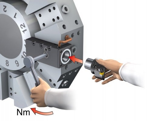
Quick change in turning centres
Turning centres have fast tool indexing but typically have a lower utilization than machining centres due to the tool change and set-up time. Use quick change holders to reduce the measuring, set-up and tool change time and instead allow for extra machining time.
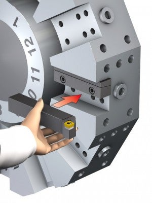
Automatic tool change in turning centres
For turning centres equipped with an ATC-MACU turret, automatic tool change is available for static and driven tool holders.
Read more about automatic tool change in turning centres.
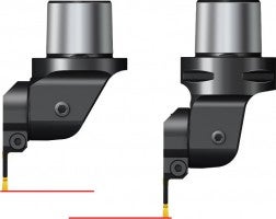
How to solve limited gauge length
Each machine has a maximum turret swing diameter. All external tool projections need to be within this diameter to allow the turret to rotate without collision. Turning cutting units have a common length and offset dimension for each Coromant Capto® size.
The clamping units for each machine turret interface are designed for standard cutting units to fit within the turret swing diameter. When using driven tool holders it is also advised to keep the tool as short as possible, not only to fit within the swing diameter but also to increase stability.
The bearings on a driven tool holder are much closer together than in a machining centre. The short gauge line reduces vibration allowing increased productivity with increased security. For external tools, which exceed the standard cutting unit length, the turret swing diameter can often be a limitation.
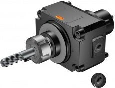
For applications requiring tool penetration, Coromant Capto® short tools are available to provide the shortest gauge line and fit within the turret clearance. Coromant Capto® short tools are without gripper grooves and are for manual tool change only.
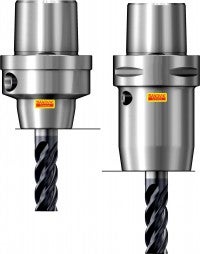
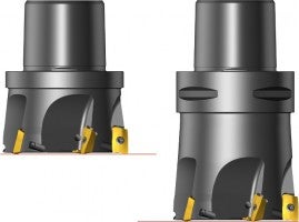
Examples of Coromant Capto® tools, without and with gripper grooves
Vertical turning centres
A vertical turning centre is a cross hybrid from the turning centre and the vertical... keyboard_arrow_right
Machining centres
Machining centres satisfy all demands for components and operations like milling,... keyboard_arrow_right
Prepared for the future
Challenge: To increase unmanned tool changing and eliminate chip-handling problems... keyboard_arrow_right
Multi-task machines - Horizontal
In a multi-task machine, you can combine several cutting processes and set-ups in... keyboard_arrow_right
