
Improving Process Security for Machining HRSA Aerospace Engine Components
Heat-resistant super alloys (HRSAs) used for aerospace engine components face extreme performance demands. What makes them incredibly durable at high pressures and temperatures in an engine environment also makes them notoriously difficult to machine. It's critical that shops know how to successfully tool up for HRSA engine components, which can run tens of thousands of dollars each, to avoid making highly expensive mistakes.
This isn't easy, especially for machine shops seeking to add HRSA capabilities. They may not have years of historical knowledge to rely on. Some lost knowledgeable workers during the pandemic. Others simply want to improve the competence of their workforce. All of them might have fundamental questions about tooling components and in many cases may only have a few trial forgings from their customers to get it right.
Ensuring process security is key to a shop’s success. To achieve repeatability and high quality when machining HRSA aerospace engine components, it's essential that shops follow some best practices. While these relate to machining HRSAs in general, each type of HRSA, engine component and feature has its own considerations, tools and techniques.
Work With the Properties of the Material
HRSAs are so difficult to machine because they resist heat, and the shear effect used to machine them generates heat. When shops machine a piece of steel, the chips that come off absorb heat from the machining process. In HRSAs, the chips resist rather than absorb the heat, sending it back into tools or the workpiece. The generated heat can turn the carbide of the cutting tool into a plasticized or sintered state, and inserts can fracture. This can damage a tool or, even worse, the engine component.
To protect tools and workpieces, it’s important that the process produces as little heat as possible when machining HRSAs. One way to do this is to use tools that cut and shear HRSAs rather than push material off. Another is to not take too much material off too quickly, like burying the cutter insert deep into the material and plowing through. Instead, a series of lighter and faster cuts is more effective and produces less heat. Most computer-aided manufacturing (CAM) packages offer this trochoidal, or dynamic, technique that makes it easier for shops to apply.
General HRSA cutting best practices apply to the different material bases. For aerospace engines, HRSA can be classified under two base elements; nickel- and titanium-based, and their cutting conditions are completely different. In most cases when turning, uncoated tools should be used to machine titanium. Titanium is chemically reactive, especially at elevated temperatures. As most coatings have titanium as well as oxygen, nitrogen and carbon which are some of its favorites, it’s possible that the titanium in the coating and workpiece can react. If they do, the titanium in the workpiece can either pull the coating off the insert through what is called adhesive wear or weld the material to the insert, essentially creating an unfavorable condition for the application.
Just the opposite, nickel-based material typically requires a tool coating. They’re a bit more difficult to machine, so SFM surface footage per minute, or the speed they’re run, needs to be about 40% to 50% slower than titanium.
Understanding how titanium and nickel HRSA bases respond to other materials can reveal additional machining benefits. While it’s becoming more of an industry standard, some shops may not know it’s possible (and advantageous) to use tools made from material other than traditional carbide to optimize the roughing and finishing processes and increase productivity. For instance, shops can use ceramics to rough machine nickel material at higher speeds. (However, NEVER machine titanium with ceramics. It can start a fire that is extremely difficult to extinguish). For finishing, shops can use polycrystalline diamond (PCD) for titanium and cubic boron nitride (CBN) for nickel-based material to machine at elevated speeds.
When preparing to work with such exotic material, some shops may not realize that they need machines that can handle it. HRSAs create a lot more forces to machine than aluminum or steel do. To save a considerable amount on setup, time and fixturing, it’s key to have the right machine for different operations.
While it may not be possible for shops to purchase new machines all at once, they can upgrade machines that will have the biggest impact. Legacy machines such as a vertical turning lathe can be used for roughing the outside and, in some cases, the inside to remove rough scale on a forging or casting. It’s smarter to invest in new machines optimized for feature-based, finishing work.

By: Bill Durow
Manager, Global Project Office for Aerospace, Space and Defense
Sandvik Coromant
www.sandvik.coromant.com
Consider the Needs of Each Feature
The complex components in an aerospace engine must be flawless, but the vastly different shapes and features of each can make this tough to accomplish. Fortunately, there are standard aerospace engine tools and inserts available from tool companies like Sandvik Coromant that precisely machine each groove, pocket and slot. These unique features and tools come with their own set of best practices and techniques.
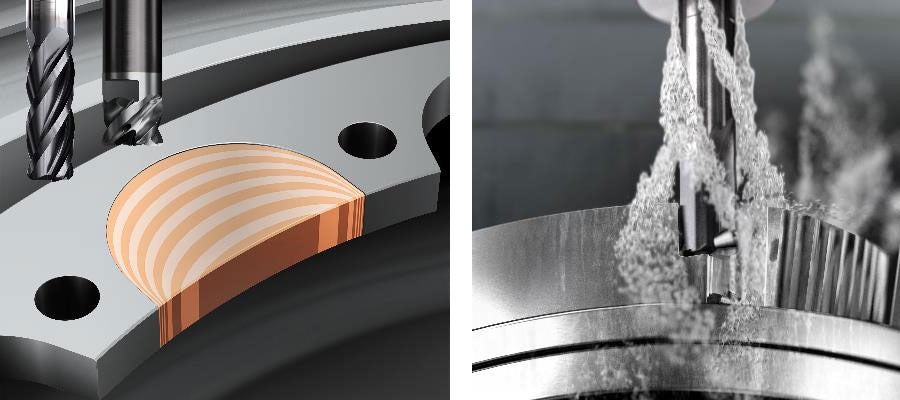
One of the most prevalent machined engine components, the turbine disc, has different types of undercuts. Optimized angled inserts can precisely machine each intricate feature. Most discs have a feature called a seal fins, which are sharp, little peaks. Standard seal fin inserts have a clearance built in to carefully machine those precise features. Using a seal fin insert, one can perform a technique in which the insert comes up, does a sweep, then goes back down in the opposite direction to avoid creating a burr or pushing the peak over.
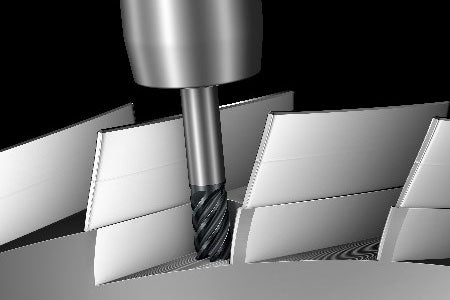
For turbine blisks that require high-feed side milling, small radial engagement allows for increased cutting speed, feed and cutting depth due to decreased heat, chip thickness and radial forces.
If machining components with slots and pockets isn’t challenging enough, blisks come with a few more factors to consider. The blade geometry and depth, the material and the machine all affect the programming and tools. A plunge-milling strategy can make machining narrow, deep slots quicker and more cost-efficient. Some unique solid carbide end mills have specifically designed geometries for plunging out material on deep, narrow slots. Then, a solid carbide end mill tool with a deeper reach can finish machine those geometries all the way down.
Some solid carbide end mills, like Sandvik Coromant’s CoroMill® Plura Gannet, have specifically designed geometries for plunging out material on deep, narrow slots. The unique Gannet concept is ideal when tool diameter is limited and a long overhang is required.
The spool, combustion casings and shaft are also common engine components. When shops source tools to machine these components, there are certain portfolio features to look for to improve process security. Selecting tool grades and geometries optimized for aerospace machining as well as damping technology has many benefits. Optimized grades can increase reliability, resist wear, improve machining accuracy and extend the life of tools and inserts. Choosing tool grades is especially important for improving process security; no one wants to scrap a component because the insert failed in the middle of finishing. Optimized geometries are sharp and can withstand high edge pressures, and damped tools improve stability, process security and component quality.
Extend Your Team, Expand Your Knowledge
Each optimized tool has its own machining technique to master. To keep learning curve short, it’s critical that shops partner with a specialist who can teach them. Some tool suppliers, like Sandvik Coromant, have engineering teams dedicated to supporting shops and their aerospace projects. These expert teams visit shops on-site and mentor them in areas they need most. They work side by side with shop teams and share the best ways to approach materials, features and components, as well as make machine recommendations, select tools, complete CAM programming, help with fixturing and more.
Some suppliers also offer in-house machining. This can be ideal for smaller shops with few machines and great ambition to grow. They can send a new piece of HRSA material they aren’t yet familiar with to an in-house machining lab. The lab can run trials and recommend the best tools, techniques and cutting data for it. Sandvik Coromant, for example, has its Training Center and Machining Application and Development Center in Mebane, North Carolina near the Raleigh-Durham area specifically for customer testing and education.
When seeking out such a specialist, it’s in a shop’s best interest to choose one that offers a comprehensive aerospace portfolio. This secures quick access to the tools and techniques specific to their needs and operations, from roughing to finishing or from a full component to a specific feature. Working closely with an expert at every step of a project not only improves process security, but it also quickly builds a shop’s historical knowledge and can often help streamline tool selection and costs.
Ensure Process Security
As aerospace machining R&D efforts advance and more optimized tools become available, new best practices and techniques will emerge. Even more will become possible for shops of all abilities and all sizes.
Machining aerospace engine components isn’t a one-size-fits-all approach. There is an opportunity to carefully consider every detail, from base material, to component, to feature, to process, to the individual tool. Each of these opportunities contain decisions that can improve process security and, in turn, improve a shop’s productivity and the quality of the engine components it can offer.
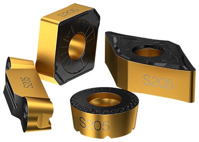
Optimized grades, such as the S205 from Sandvik Coromant, can increase reliability, resist wear, improve machining accuracy and extend the life of tools and inserts. This is especially important for process security; no one wants to scrap a component because the insert failed in the middle of finishing.
B
ill Durow is the manager of the Global Project Office for Aerospace, Space and Defense at Sandvik Coromant, a tool manufacturer and machining solutions and knowledge provider for the metalworking industry. He can be reached at contact.coromant.us@sandvik.com
.
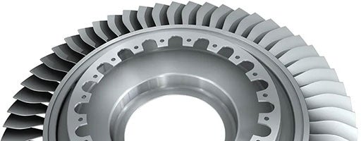
Blisks located on the cold compressor side of the engine are made of titanium, while the hot turbine side requires blisks made of heat-resistant super alloys.
